Orange Pi Zero - WiringOP
Zápisník experimentátora
Hierarchy: Orange Pi
WiringOP is a modification to the WiringPi library for Orange Pi. Allows GPIO control on the board. The outputs on the board are located on a 26-pin connector. Orange Pi Zero is sold without a soldered connector. It needs to be soldered to the pins could work. It is up to you to decide which connector you are choosing. I preferred the male version, because one such connector is already attached to the board.

Used parts
We will need the following components:
- Orange Pi Zero (link) - use the version with 512 MB of RAM.
- SD card - You need to use the Class 10 SD card. You need a size of 8 - 16 GB. The Armbian operating system must be installed on the SD card. I have used the version of Armbian 5.30, Debian Jessie 3.4.113.
- Power supply with micro USB connector - At home you will surely have a mobile phone charger. Orange Pi Zero does not need a special power supply. Just check whether it is able to deliver 1.5 - 2 A.
- Ethernet cable or Wi-Fi - This depends on how you set Orange Pi Zero. Connecting to a router via an Ethernet cable is the simplest way. If you have set up Wi-Fi, you can have your Orange Pi Zero placed anywhere in the apartment.
- Mini breadboard (link)
- Resistor 4k7
- Blue LED diode
Installation of the WiringOP library
The library source code can be found at https://github.com/zhaolei/WiringOP. Move to your home directory and use git to create a copy of the directory. It's not a typo, in a remote repository is really a branch h3. Then change the permissions on the file build and install the library.
git clone https://github.com/zhaolei/WiringOP.git -b h3
cd WiringOP
chmod +x ./build
sudo ./build
Checking the status of GPIO pins
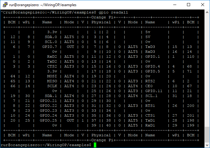
After installation, run the gpio readall command. You get a table of the current GPIO pin settings. The table may seem unclear at first glance, but only the wPi, Mode, and V columns are important to you. It is also unclear that you have 40 pins in the table and only 26 on the board. That means you ignore the pins with the number greater than 26.
Setting GPIO pin
The following examples are set for pin 7. Its number can be found in the wPi column in GPIO.7 line. If you connect blue LED and 4k7 resistor to pin 7, you will also see the result. If you leave the pins unconnected, you can check the result with the gpio readall command.
gpio mode 7 out- Sets the pin as output.gpio write 7 on- Sets the logical one to pin.gpio write 7 off- Sets the logical zero to pin.
gpio program has many different parameters. These served only to show the possibilities.
Blink in C++
We can use the library in our programs. For example, Blink in C++ looks like this. The program shows inspiration in the Arduino development environment.
#include <stdio.h>
#include <wiringPi.h>

#define LED 7

int main (void)
{
  printf ("Orange Pi Zero blink\n");

  wiringPiSetup();
  pinMode(LED, OUTPUT);

  for (;;)
  {
    digitalWrite(LED, HIGH); // On
    delay(500);              // mS
    digitalWrite(LED, LOW);  // Off
    delay(500);
  }
  return 0;
}
We compile it with the command.
gcc -o blink blink.c -lwiringPi
Run it with the command.
sudo ./blink
We have to run the program with superuser rights because it controls GPIO ports.
Source code
The source code is located on the GitHub server.
03.10.2017