10-bit PWM from the ATtiny85
Zápisník experimentátora
Hierarchy: ATtiny85
The ATtiny85 microcontroller has two 8-bit timers. Using them can be controlled dimming of LEDs. 8 bit is not enough if you want to have a brightness change adapted to the human eye. Gamma correction causes visible jumps in brightness, especially at low brightness. The ATtiny85 microcontroller can with timer 1 produce even better resolution. In this article, we'll show you how to do it.
8-bit dimming
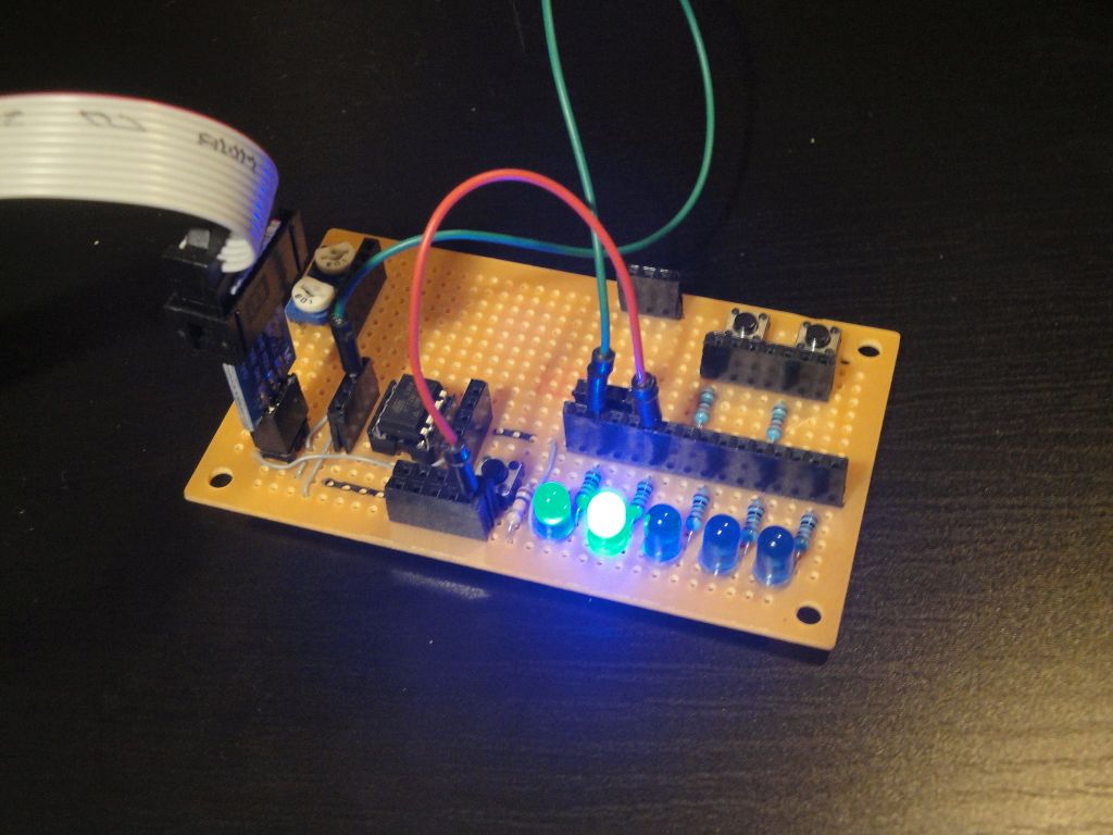
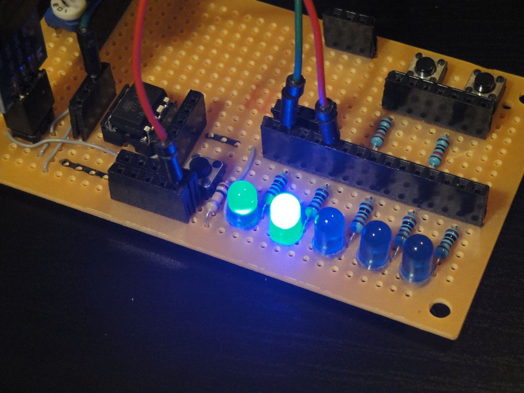
Here are some examples of LED dimmers I've created. But they all suffer the same defect. Jumps in brightness are visible at low brightness. You can see the examples with videos that make it very easy to see the defects.
16-bit dimming
If you have a 16-bit timer microcontroller, LED dimming is easier. You only have to set the appropriate timer mode and the microcontroller will take care of everything. An example with higher bit resolutions can be found on these pages.
10-bit PWM from ATtiny85
Inspiration for this code I found on the Internet in the blog 10 or 12-bit DAC from the ATtiny85. The author describes the bit increasing technique in detail. It works in such a way that the timer 1 has specific features that allow it to be set to HIGH and LOW. With the interrupt at the appropriate intervals, the timer is set by first setting in one cycle to HIGH and in the following cycle to an 8-bit PWM value. The result is, for example, 512 values instead of 256. The article explains 10-bit and 12-bit resolution, but it does not differ much from this algorithm.

According to the blog I slightly modified two programs. In the pwm10bit and pwm12bit files you will find my examples.
volatile int Dac = 0;
volatile int Cycle = 0;

// Overflow interrupt
ISR (TIMER1_OVF_vect) {
  static int remain;
  if (Cycle == 0)
    remain = Dac;
  if (remain >= 256) {
    OCR1A = 255; // high (Table 12-2)
    remain = remain - 256;
  }
  else {
    OCR1A = remain;
    remain = 0;
  }
  Cycle = (Cycle + 1) & 0x03;
}

void analogWrite10 (int value) {
  cli();
  Dac = value;
  sei();
}

void setup() {
  // Top value for high (Table 12-2)
  OCR1C = 255;
  // Timer/Counter1 doing PWM on OC1A (PB1)
  TCCR1 = 1 << PWM1A    // Pulse Width Modulator A Enable
          | 1 << COM1A0 // OC1x cleared on compare match. Set when TCNT1 = $00
          | 1 << CS10;  // PWM clock = CK
  TIMSK |= 1 << TOIE1; // Timer/Counter1 Overflow Interrupt Enable
  pinMode(1, OUTPUT);
}

void loop () {
  for (int i = 0; i < 100; i++) {
    analogWrite10(i);
    delay(10);
  }
}
Gamma correction
Previous examples do not affect the human eye naturally. With gradual increase of the duty cycle, the brightness of the diode increases very quickly so that you can not see the changes of brightness afterwards. Therefore, the brightness needs to be adjusted using gamma correction. I wrote a separate article about calculating the gamma value correction table.
Typically, a calculated table for 256 8-bit values is used. However, such a table is not enough for more bits, so we need to use a 16-bit value, for example, and have as many values as possible in the table. Here we come across the memory limits of ATtiny85 microcontroller. If we wanted to save the whole table for 10-bit PWM, we would need 1024 x 2 bytes, which will greatly reduce the space for the program itself. Therefore, it is advisable to have the table smaller and missing values linearly interpolated. Examples can be found in gamma_255, gamma_65535, and gamma_interpolation.
The final program
When all this information is put together, the result will be the program that is in the pwm10bithuman file. It combines the previous program with gamma correction and results in a nice dimmer that does not have visible jumps in the brightness in low PWM values.
const uint16_t PROGMEM gamma_8b[] = {
  0,    0,    0,    0,    1,    1,    2,    3,    4,    6,    8,   10,   13,   16,   19,   24,
  28,   33,   39,   46,   53,   60,   69,   78,   88,   98,  110,  122,  135,  149,  164,  179,
  196,  214,  232,  252,  273,  295,  317,  341,  366,  393,  420,  449,  478,  510,  542,  575,
  610,  647,  684,  723,  764,  806,  849,  894,  940,  988, 1037, 1088, 1140, 1194, 1250, 1307,
  1366, 1427, 1489, 1553, 1619, 1686, 1756, 1827, 1900, 1975, 2051, 2130, 2210, 2293, 2377, 2463,
  2552, 2642, 2734, 2829, 2925, 3024, 3124, 3227, 3332, 3439, 3548, 3660, 3774, 3890, 4008, 4128,
  4251, 4376, 4504, 4634, 4766, 4901, 5038, 5177, 5319, 5464, 5611, 5760, 5912, 6067, 6224, 6384,
  6546, 6711, 6879, 7049, 7222, 7397, 7576, 7757, 7941, 8128, 8317, 8509, 8704, 8902, 9103, 9307,
  9514, 9723, 9936, 10151, 10370, 10591, 10816, 11043, 11274, 11507, 11744, 11984, 12227, 12473, 12722, 12975,
  13230, 13489, 13751, 14017, 14285, 14557, 14833, 15111, 15393, 15678, 15967, 16259, 16554, 16853, 17155, 17461,
  17770, 18083, 18399, 18719, 19042, 19369, 19700, 20034, 20372, 20713, 21058, 21407, 21759, 22115, 22475, 22838,
  23206, 23577, 23952, 24330, 24713, 25099, 25489, 25884, 26282, 26683, 27089, 27499, 27913, 28330, 28752, 29178,
  29608, 30041, 30479, 30921, 31367, 31818, 32272, 32730, 33193, 33660, 34131, 34606, 35085, 35569, 36057, 36549,
  37046, 37547, 38052, 38561, 39075, 39593, 40116, 40643, 41175, 41711, 42251, 42796, 43346, 43899, 44458, 45021,
  45588, 46161, 46737, 47319, 47905, 48495, 49091, 49691, 50295, 50905, 51519, 52138, 52761, 53390, 54023, 54661,
  55303, 55951, 56604, 57261, 57923, 58590, 59262, 59939, 60621, 61308, 62000, 62697, 63399, 64106, 64818, 65535
};

volatile int Dac = 0;
volatile int Cycle = 0;

// Overflow interrupt
ISR (TIMER1_OVF_vect) {
  static int remain;
  if (Cycle == 0)
    remain = Dac;
  if (remain >= 256) {
    OCR1A = 255; // high (Table 12-2)
    remain = remain - 256;
  }
  else {
    OCR1A = remain;
    remain = 0;
  }
  Cycle = (Cycle + 1) & 0x03;
}

void analogWrite10 (int value) {
  cli();
  Dac = value;
  sei();
}

void setup() {
  // Top value for high (Table 12-2)
  OCR1C = 255;
  // Timer/Counter1 doing PWM on OC1A (PB1)
  TCCR1 = 1 << PWM1A    // Pulse Width Modulator A Enable
          | 1 << COM1A0 // OC1x cleared on compare match. Set when TCNT1 = $00
          | 1 << CS10;  // PWM clock = CK
  TIMSK |= 1 << TOIE1; // Timer/Counter1 Overflow Interrupt Enable
  pinMode(1, OUTPUT);
}

void loop () {
  for (int i = 0; i < 1024; i++) {
    uint16_t y = pgm_read_word(&gamma_8b[i / 4]);
    uint16_t z1 = (i / 4 == 0) ? 0 : pgm_read_word(&gamma_8b[i / 4 - 1]);
    uint16_t z = (y - z1) / 4 * (i % 4 + 1) + z1;

    // without gamma correction
    //analogWrite10(i);

    // with gamma correction
    analogWrite10(z >> 6);

    delay(8000 / 1024);
  }
}
Video
Video with 10-bit PWM for ATtiny85. In the video, I tried to capture mostly dimming at low brihtness, which is exactly where the brightness jumps are visible at 8-bit resolution due to the influence of gamma correction. The two extra bits are enough for the eye to hardly notice.
Source code
The source codes are located on the GitHub server.
Video
02.01.2018