How to Destroy an External EEPROM
Zápisník experimentátora
Hierarchy: Externá EEPROM
In the previous article, we looked at data from an external EEPROM. It was just curiosity. The real reason for acquiring EEPROM was a memory test. In today's article, we are subjecting the memory to a devastating test in which we will write to it until it stops working.
Used components
For this experiment you only need a few components:
- Arduino Pro Mini (link) - I used it because it fits well to the smallest breadboard.
- Breadboard 400 Holes (link) - On it we have enough space for the two microswitches.
- Convertor CP2102 USB to Serial (link) - The converter is used to program the Arduino.
- EEPROM 24C32WP
- SOIC8 to DIP8 adapter (link) - Because the EEPROM is in the SOIC8 package, an adapter is needed to plug it into a breadboard.
- OLED display 0.96 (link) - During the test, the display shows the current status of the test. The display is connected according to this article.
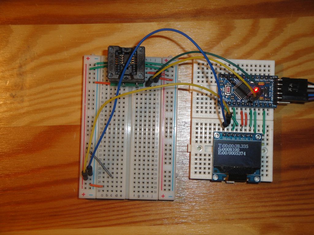
The Arduino is designed to have an I2C (extraordinary on extra pins in the middle of the Arduino) pin header with holes to make it easy to connect with the EEPROM via two connecting wires.
The EEPROM is connected to the power supply and the address pins A0, A1 and A2 are not connected. This only applies to this particular type of EEPROM. Others usually have to connect these pins to the GND or VCC to set the I2C address. You should always check the datasheet for the specific type and set it according to it.
Physical boundaries of EEPROM
EEPROM memories are designed to be safely overwrited several times, and the manufacturer guarantees the number of write times and the amount of time the memory stores stored information. Typically, there are 1 million Erase/Write cycles and 40-100 years of data retention. Under normal conditions it is more than sufficient. In order to damage the memory, you would have to overwrite the same place at least a million times. But it's not as simple, that after a million times the cell is damaged. The inside of the memory are hidden a number of specifically tailored transistors that can store electrical charge in their structure and the physical conditions during overwriting cause the material of the transistors to gradually degrade until the charge can not be stored in the transistors.
There are more factors to keep data, but according to manufacturers the temperature is the most important parameter. With the increasing temperature, the amount of Erase/Write cycles decreases. In this test we look at the possibilities of simulating such gradual destruction and we will find out where reality is.
The sketch
Since I did not know how much time it takes to destroy the memory and what exactly is going on, I made circuit with the OLED display. The display shows:
- time
- number of Erae/Write cycles
- the number of detected errors
This makes it easy to find out what's happening with the memory. The OLED display is connected to to Arduino pins, which seemed to me best for the Arduino Pro Mini and two minibreadboards. The connection will not be described here, it is exactly the same as in the OLED display connection article.
Let's describe a few variables in the program. I use the tbuffer, sbuffer, and ebuffer variables to display on the display. The source code shows the examples of specific data in it. Variable step, errors, and steperrors, in turn, collect data about a particular cycle and the amount of errors found. The data0 and date1 fields contain sample data that are written to the EEPROM.
#include <U8g2lib.h>
#include <extEEPROM.h>

U8G2_SSD1306_128X64_NONAME_1_4W_HW_SPI u8g2(U8G2_R0, /* cs=*/ A3, /* dc=*/ A2, /* reset=*/ A1);
char tbuffer[]="t:xxx:xx:xx.xxx";
char sbuffer[]="s:10000000";
char ebuffer[]="e:10/1000000";
unsigned long step=0;
unsigned long errors=0;
int steperrors;
extEEPROM eep(kbits_32, 1, 16);
unsigned char data0[] = {0x00,0x00,0x00,0x00,0x00,0x00,0x00,0x00,0x00,0x00};
unsigned char data1[] = {0xff,0xff,0xff,0xff,0xff,0xff,0xff,0xff,0xff,0xff};
unsigned char d[10];
int datpos=0;
The setup function initializes the display and connects to the EEPROM. If it can not connect, the program will end in an infinite loop.
void setup() {
  u8g2.begin();
  u8g2.setFont(u8g2_font_ncenB10_tr);
  uint8_t eepStatus = eep.begin(twiClock400kHz);
  if(eepStatus) {
    while (1);
  }
}
In the function loop, I copy the data into EEPROM. I rewrite the first 10 bytes to complete the test in a reasonable time. Any increase in the number of rewritten cells would significantly increase the resulting time.
void loop() {
  //eeprom 1st 10 bytes
  steperrors=0;
  eep.write(0, datpos==0 ? data0 : data1, 10);
  eep.read(0,d,10);
  for(int i=0;i<10;i++) {
    unsigned char *data = datpos==0 ? data0 : data1;
    if(d[i]!=data[i]) {
      steperrors++;
      errors++;
    }
  }
  datpos++;
  datpos%=2;

  // update display
  step++;
  if(step%100==0)
    drawFrame();
}
The last function displays three lines on the display. The first row contains a time in hours, minutes, seconds, and milliseconds. Hours can be longer than 24 hours. It's worth mentioning how the time for a particular item is calculated from the internal milliseconds. I create a listing using the sprintf function, which is virtually unknown in the world of Arduino, but in the c++ world, it is a completely normal function with a variable number of parameters. The output is written into the character field and can be formatted in a nice way using formatting characters.
void drawFrame() {
  unsigned long m=millis();
  sprintf(tbuffer,"T:%02d:%02d:%02d.%03d",
          (int)(m/1000L/3600),
          (int)((m/1000L/60)%60),
          (int)((m/1000L)%60),
          (int)(m%1000L));
  sprintf(sbuffer,"S:%07lu",step);
  sprintf(ebuffer,"E:%02d/%07lu",steperrors,errors);
  u8g2.firstPage();
  do {

  u8g2.drawStr(0, 12, tbuffer);
  u8g2.drawStr(0, 24, sbuffer);
  u8g2.drawStr(0, 36, ebuffer);

  } while ( u8g2.nextPage() );
}
How testing was running
I will not strain you, testing was a huge boredom. The program had to run around 20 million cycles until the errors started to appear. It took two days, during which I was no longer in doubt, that somewhere in the program I made an errorg. And after two days, an errors began to show. It was not visible on the display, but when I displayed the EEPROM content using the program from the previous article, it was nice to see that three cells out of ten started to fail.
The failure was manifested by the fact that a few bits were no longer able to hold information. In the EEPROM the information is stored so that the value 1 is a charge-free transistor and the value 0 is the charged transistor. So if you want to make an error, you have to write a value of 0 to the cell. The value 0xff is always written correctly because it only deletes all electrical charge from the transistor. Some cells could not hold the charge, others held it for a few seconds or even hours. In practice, it looked like the contents of the cells were the same after the recording
0x0000 00 00 00 00 00 01 00 00 00 00
and after a few minutes, for example, as follows.
0x0000 00 00 00 00 00 07 01 04 00 00
How long does EEPROM last?
My findings on the EEPROM are basically consistent with what other people did. For example, EEPROM tests directly in the ATmega328P microcontroller show very similar behavior. Cycle counts varied from 10 million to 20 million. Interestingly, the memory was slightly regenerating after a few days and was able to keep some data better. Of course, it was not reliable, but something in the silicon structure causes the interruption of writing to have a good effect on data retention.
The rest of the cells in EEPROM are still fine, so in theory I could still use this memory.
Source code
The source code is located on the GitHub server.
01.09.2017