433 MHz radio modules using the VirtualWire library
Zápisník experimentátora
Each of us met with incredibly inexpensive Ebay modules that allow wireless communication between Arduinos. The offer is incredibly varied and we look at the cheapest in this article. A dual transmitter and receiver that communicates at 433 MHz.
Purchase of parts
Arduino Pro Mini and Arduino Mega are used in the photos. It does not limit you, you can use any Arduino.
- Arduino Pro Mini (link) - I used this Arduino as a receiver.
- Arduino Mega (link) - I used this Arduino as a transmitter.
- Mini Breadboard (link) - I plugged the radio modules into this breadboard.
- Radio modules (link) - 433 MHz radio modules are usually sold in pairs. Although they have different designations, they seem to be virtually identical. They have the following names: XD-RF-5V, MX-JS-05V, XD-FST, MX-FS-03v, XY-MK-5V, FS1000A. Radio modules are sold without an antenna. This has a great impact on the broadcast range. If you want to transmit even more meters, you must attach the antenna to both modules.
Antenna length
Here the data differs slightly on the Internet, but it is usually 17.5 cm (alternatively 15 cm). This length must not be strictly observed in amateur conditions. Basically, every piece of wire you attach will significantly improve the properties of the transmitter.
VirtualWire
You do not find this library in your library manager and you need to install it from a zip file. The library home page is http://www.airspayce.com/mikem/arduino/VirtualWire/index.html. The author writes that the library is no longer developing and has been replaced by the RadioHead library. This is a library from the same author and we look at it in the next article. This does not bother us and install it in the [username]\documents\arduino\libraries\virtualwire directory.
Program (sketch)
These two simple programs communicate together. The first sends incrementing numbers to easily check connection failures, and the second program receives these numbers and displays them on the serial port. You see in the statement how many characters were received and what is the difference with the previous message. If there is a difference of 1, then there was no outage. If the number is bigger, then so many messages have gone out. Then it's easy to manipulate both Arduinos and watch what happened.
With an attached antenna, the modules were able to communicate at a distance of 6 meters, with minor obstructions in the form of doors. A greater distance and through a concrete wall has been communication more difficult.
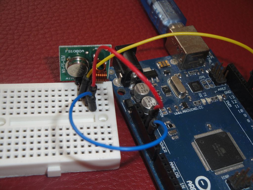
Transmitter
The data pin is connected to pin 12 in Arduino. If this does not suit you, you can change it with function vw_set_tx_pin.
#include <VirtualWire.h>

char buffer[10];
int idx=0;

void setup()
{
  // Initialize the IO and ISR
  vw_setup(2000); // Bits per sec
  pinMode(LED_BUILTIN,OUTPUT);
  Serial.begin(9600);
}

void loop()
{
  sprintf(buffer,"%d",idx);
  idx++;

  send(buffer);
  //send("Hello!");
  delay(1000);
}

void send (char *message)
{
  digitalWrite(LED_BUILTIN,HIGH);
  Serial.print("Transmited: ");
  Serial.println(message);
  vw_send((uint8_t *)message, strlen(message));
  vw_wait_tx(); // Wait until the whole message is gone
  digitalWrite(LED_BUILTIN,LOW);
}
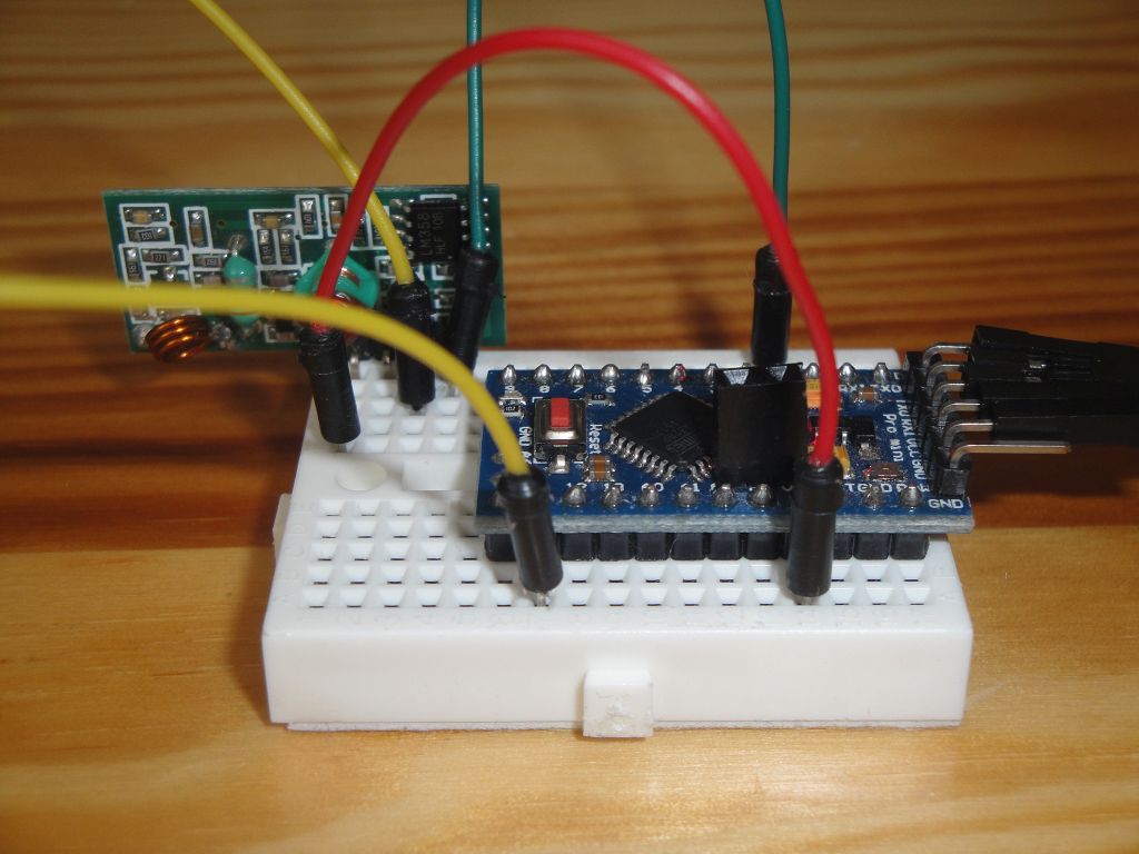
Receiver
The data pin is connected to pin 11 in Arduine. If this does not suit you, you can change it with function vw_set_rx_pin.
#include <VirtualWire.h>

char message[VW_MAX_MESSAGE_LEN]; // a buffer to store the incoming messages
byte messageLength = VW_MAX_MESSAGE_LEN; // the size of the message
int last_idx = 0;

void setup()
{
  Serial.begin(9600);

  Serial.println("Device is ready");

  // Initialize the IO and ISR
  vw_setup(2000); // Bits per sec

  vw_rx_start(); // Start the receiver
}

void loop()
{
  if (vw_get_message(message, &messageLength)) // Non-blocking
  {
    message[messageLength] = 0;
    Serial.print("Received(");
    Serial.print(messageLength);
    Serial.print("}: ");
    Serial.print(message);

    Serial.print(" (");
    int idx=atoi(message);
    Serial.print(idx>last_idx ? "+" : "-");
    Serial.print(idx-last_idx);
    last_idx=idx;
    Serial.print(")");
    Serial.println();
  }
}
Source code
The source code is located on the GitHub server.
- https://github.com/RoboUlbricht/arduinoslovakia/tree/master/433/virtualwire/transmitter01
- https://github.com/RoboUlbricht/arduinoslovakia/tree/master/433/virtualwire/receiver01
15.07.2017