16-bit PWM resolution for Arduino
Zápisník experimentátora
Hierarchy: Časovač (timer)
Arduino has implicitly all PWM channels set to 8-bit resolution. This is not the maximum resolution. Timer1 can use up to 16-bit resolution. In this article, we'll show you how to do it.
Purchase of components
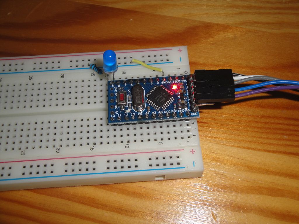
Arduino Pro Mini is on the photo. It does not limit you, you can use basically any Arduino.
- Arduino Pro Mini {linkArduino} - I used this Arduino.
- Breadboard {linkBreadboard} - It is used to insert all components.
- Blue LED - Blue color is suitable because the LED has high brightness and you can also see fine changes in brightness.
- Resistor 1k {linkR} - The resistor limits the current flowing through the LED. Because we use a high-luminous LED, just a couple of milliamps is enough for us.
Connection is simple. The LED will be connected to pin 9, because this pin has output from timer1. We will connect it using a resistor to GND output from Arduino. We could also use pin 10, which is connected to the same timer. We need to use either of these pins because only timer1 has a 16 bit resolution.
PWM
Arduino Uno has three timers. They can be used for various tasks. One is to generate a PWM signal. The principle is simple. A clock signal comes into the timer. This can be reduced to the desired level using the prescaler. In our case, we will generate a high-resolution signal and therefore we will use a clock signal that is equal to the Arduino clock frequency.
The timer sets the appropriate PWM mode. Depending on the selected mode, several additional registers need to be set. But two values are still used. The first determines when the signal switches from HIGH to LOW. And the second determines when it comes back. The relationship between HIGH and LOW is called duty cycle and determines, for example, the brightness of our LED. The longer the output will be in the HIGH state, the brighter the LED will light up.
Because we need to change the resolution, we have to choose a mode that allows us to modify the second value. This value affects the signal frequency. We have two modes to choose from, and in this case we will use mode 14. For details on setting this mode, see ATmega328P microcontroller datasheet at timer1.
Examples
I wrote two sample sketches. The first one sets the 16-bit resolution and sets the brightness in low values. The second example is interactive and you can set your own resolution and brightness.
16-bit PWM
Function setupPWM16 sets the PWM resolution. The pins are set as output, the appropriate PWM shape is set, the mode and the prescaler is set to the same value as the Arduino clock signal. What's important is the value you set in ICR1. The timer will count from zero to your value and then start again from zero. The signal will be switched at this value and at the value you set in the OCR1A register. The lower the OCR1A value, the less LED will light up. In the loop function, you can see this registry setting on the first 2000 values.
It depends on your eyes whether you will see a flashing diode on such a high resolution. For example, I see it, but it's enough to reduce the resolution to 15 bits and my eyes stop to sense blinking. You can do this by changing the value in the ICR1 registry. For a better explanation, see the second example.
void setup() {
  Serial.begin(9600);
  setupPWM16();
}

uint16_t icr = 0xffff;

void loop() {
  Serial.println("*");
  for (uint16_t i = 0; i < 2000; i++)
  {
    analogWrite16(9, i);
    delay(2);
  }
}

void setupPWM16() {
  DDRB  |= _BV(PB1) | _BV(PB2);       /* set pins as outputs */
  TCCR1A = _BV(COM1A1) | _BV(COM1B1)  /* non-inverting PWM */
        | _BV(WGM11);                 /* mode 14: fast PWM, TOP=ICR1 */
  TCCR1B = _BV(WGM13) | _BV(WGM12)
        | _BV(CS10);                  /* prescaler 1 */
  ICR1 = icr;                         /* TOP counter value (freeing OCR1A*/
}

/* 16-bit version of analogWrite(). Works only on pins 9 and 10. */
void analogWrite16(uint8_t pin, uint16_t val)
{
  switch (pin) {
    case  9: OCR1A = val; break;
    case 10: OCR1B = val; break;
  }
}
Interactive PWM
You can use the second example to better adjust the resolution and the duty cycle of PWM generated signal. Run the serial port monitor. Enter the letter a-i to set the resolution. You can set 8-16 bits. Enter a number from 0-65535 to set the duty cycle. But you have to know that if you have an 8-bit resolution, the maximum value is 255. With a 16-bit resolution, the maximum value is 65535. Try different combinations of settings and see what you can recognize with your eyes. Every eye is different, and someone sees weaker bright changes in brightness and someone recognize diode flashes at a lower resolution than any other person.
uint16_t icr = 0xffff;
String line;

void setup() {
  Serial.begin(9600);
  Serial.println("Arduino interactive 16-bit PWM");
  Serial.println("");
  Serial.println("Resolution: a-i (8-16 bit)");
  Serial.println("Value: number 0-65535");
  OCR1A=0;
  OCR1B=0;
  setupPWM16(16);
}

void loop() {
  if(Serial.available()>0) {
    line=Serial.readString();
    line.trim();
    if(line.length()) {
      Serial.print("Command:");
      Serial.println(line);
      if('a'<=line[0] && line[0]<='i') {
        int resolution = 8 + line[0] - 'a';
        Serial.print("Resolution:");
        Serial.println(resolution);
        setupPWM16(resolution);
      }
      else {
        uint16_t value = line.toInt();
        Serial.print("Value:");
        Serial.println(value);
        analogWrite16(9,value);
      }
    }
  }
}

void setupPWM16(int resolution) {
  switch(resolution) {
    case 16:icr=0xffff;break;
    case 15:icr=0x7fff;break;
    case 14:icr=0x3fff;break;
    case 13:icr=0x1fff;break;
    case 12:icr=0x0fff;break;
    case 11:icr=0x07ff;break;
    case 10:icr=0x03ff;break;
    case  9:icr=0x01ff;break;
    case  8:icr=0x00ff;break;
    default:icr=0x00ff;break;
  }
  DDRB  |= _BV(PB1) | _BV(PB2);       /* set pins as outputs */
  TCCR1A = _BV(COM1A1) | _BV(COM1B1)  /* non-inverting PWM */
        | _BV(WGM11);                 /* mode 14: fast PWM, TOP=ICR1 */
  TCCR1B = _BV(WGM13) | _BV(WGM12)
        | _BV(CS11);                  /* prescaler 1 */
  ICR1 = icr;                         /* TOP counter value (freeing OCR1A*/
  Serial.print("ICR1:");
  Serial.println(icr);
}

/* 16-bit version of analogWrite(). Works only on pins 9 and 10. */
void analogWrite16(uint8_t pin, uint16_t val)
{
  switch (pin) {
    case  9: OCR1A = val; break;
    case 10: OCR1B = val; break;
  }
}
Source code
The source code is located on the GitHub server.
04.07.2019