DS1307 for beginners
Zápisník experimentátora
Hierarchy: DS1307 Hodiny reálneho času
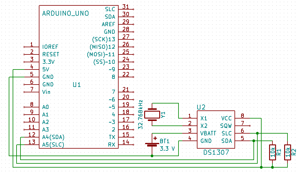
In this article we will explain the basics of using the integrated circuit DS1307. We will learn to set the time and learn how to read the time on the circuit. We'll explain how to use the entire RAM that the IC provides. Part of the explanation will be a little trip to the depths of the I2C protocol.
Used parts
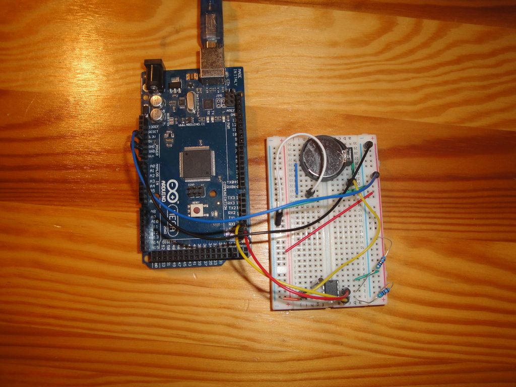
I used the following components:
- Arduino Mega 2560 ((link)
- DS1307 (link)
- Breadboard (link)
- 2x 10k resistor
- Battery CR2032 (link)
- Battery Socket Holder (link)
The sketches
I created three examples:
- set_time - This example shows setting the time in an integrated circuit using a macro with a timestamp at the time of compilation. The program is only slightly modified compared to the original example, directly from the library.
- get_time - Reading time from an integrated circuit. The program is only slightly modified compared to the original example, directly from the library.
- get_ram - The DS1307 has 64 bytes of RAM memory. Only 8 bytes are used for counting the time. You can use the rest to save your settings. In this example, I show reading the entire RAM and filling the RAM with sample data.
Before working with the circuit itself, it is advisable to test whether it is visible on the I2C bus. You may have accidentally swapped connecting wires, or you made some other mistake. The i2c_tester program is suitable for testing, so you can see all I2C slave devices on the bus. If you have made the circuit on the breadboard using my instructions, you will only see one device. If you used the finished module, you will see two devices because the module is usually also equipped with an external EEPROM.
set_time
The first action you have to do after purchasing the integrated circuit is setting the time. The easiest way is to set the same time as you have on your computer. You could also do this directly by entering values for hours, minutes and seconds, but there is a more convenient way. Using the macros __TIME__ and __DATE__. These contain the text string with the current time at the time of program compilation. Because the compilation and uploading of the program into the Arduino takes place in sequence, the time in the integrated circuit will be only a few seconds different from the time you have on your computer.
There are two functions in the program to convert time from text to time. Function getDate gets the date and getTime gets the time. They both use function sscanf. Text strings have the same form in each compiler, so do not worry that the program would not work because you have a different language mutation on your computer than English.
When setting this time, you need to remember what time you enter into the integrated circuit. It's so-called local time. So it is a time that is subject to regular changes in the summer when it moves for one hour. But as example to adjust the time it is enough. Later, we'll show you how to deal with summer time.
#include <Wire.h>
#include <TimeLib.h>
#include <DS1307RTC.h>

const char *monthName[12] = {
  "Jan", "Feb", "Mar", "Apr", "May", "Jun",
  "Jul", "Aug", "Sep", "Oct", "Nov", "Dec"
};

tmElements_t tm;
bool parse=false;
bool config=false;

void setup() {

  Serial.begin(9600);
  while (!Serial) ; // wait for Arduino Serial Monitor
  delay(200);

  Serial.print("Sketch compile time __TIME__='");
  Serial.print(__TIME__);
  Serial.print("', __DATE__='");
  Serial.print(__DATE__);
  Serial.println("'");

  // get the date and time the compiler was run
  if (getDate(__DATE__) && getTime(__TIME__)) {
    parse = true;
    // and configure the RTC with this info
    if (RTC.write(tm)) {
      config = true;
    }
  }

  if (parse && config) {
    Serial.println("Parse and write OK.");
  } else if (parse) {
    Serial.println("DS1307 Communication Error");
    Serial.println("Please check your circuitry");
  } else {
    Serial.println("Could not parse info from the compiler");
  }
}

void loop() {
if(parse && config) {
  time_t t=RTC.get();
  Serial.print("RTC.get()=");
  Serial.println(t);
  }
delay(1000);
}

bool getTime(const char *str)
{
  int Hour, Min, Sec;

  if (sscanf(str, "%d:%d:%d", &Hour, &Min, &Sec) != 3) return false;
  tm.Hour = Hour;
  tm.Minute = Min;
  tm.Second = Sec;
  return true;
}

bool getDate(const char *str)
{
  char Month[12];
  int Day, Year;
  uint8_t monthIndex;

  if (sscanf(str, "%s %d %d", Month, &Day, &Year) != 3) return false;
  for (monthIndex = 0; monthIndex < 12; monthIndex++) {
    if (strcmp(Month, monthName[monthIndex]) == 0) break;
  }
  if (monthIndex >= 12) return false;
  tm.Day = Day;
  tm.Month = monthIndex + 1;
  tm.Year = CalendarYrToTm(Year);
  return true;
}
get_time
When we have the time set, we can read it from the integrated circuit. We have two options, in what form we gain time. In this example, the time obtained is parsed into the tmElements_t structure. The function read is used for parsing. But we can also get time as time_t. That's what the function get is for. It all depends on the further processing of the time in the program, which form we choose. In this case, we were more suited to the parsed form in tmElements_t. In this example, I added a conversion between both forms using the function makeTime to see that change is possible at any time.
#include <Wire.h>
#include <TimeLib.h>
#include <DS1307RTC.h>

void setup() {
  Serial.begin(9600);
  while (!Serial) ; // wait for serial
  delay(200);
  Serial.println("DS1307RTC Get Time");
  Serial.println("-------------------");
}

void loop() {
  tmElements_t tm;
  time_t t;

  if (RTC.read(tm)) {
    t=makeTime(tm);
    Serial.print("Ok, Time=");
    print2digits(tm.Hour);
    Serial.write(':');
    print2digits(tm.Minute);
    Serial.write(':');
    print2digits(tm.Second);
    Serial.print(", Date(D/M/Y)=");
    Serial.print(tm.Day);
    Serial.write('/');
    Serial.print(tm.Month);
    Serial.write('/');
    Serial.print(tmYearToCalendar(tm.Year));
    Serial.print(", time_t=");
    Serial.print(t);
    Serial.println();
  } else {
    if (RTC.chipPresent()) {
      Serial.println("The DS1307 is stopped. Please run the set_time");
      Serial.println("sketch to initialize the time and begin running.");
      Serial.println();
    } else {
      Serial.println("DS1307 read error! Please check the circuitry.");
      Serial.println();
    }
    delay(9000);
  }
  delay(1000);
}

void print2digits(int number) {
  if (number >= 0 && number < 10) {
    Serial.write('0');
  }
  Serial.print(number);
}
get_ram
In the last example we will directly read the contents of the RAM in the integrated circuit. Since the library used does not provide any functions for this, we need to add them. To learn a little about object programming, I derived the DS1307RTCex from the DS1307RTC class. I added a variable ram into the class to have the place for the copy of entire RAM in the integrated circuit. I added three functions that will do all the work.
- readRam - Using this function, we read the RAM content. You see a cycle that repeats four times and reads 16 bytes. We have to do this because the implementation of I2C in Arduino does not allow us to read 64 bytes at once. In the cycle, note that if we want to read through I2C, we must first send an address and then we can read 16 bytes from it. Just set the address for the start of the block, because the integrated circuit moves it by itself. There are two strange c++ constructions for you.
*ptr=ram- I assigned the beginning of array ram into the variable ptr. In C++ ptr and the ram are pointers so I can write this. The helper variable ptr serves to move over the individual array elements and write the readings to it.*ptr++=Wire.read()- This entry means that it stores the read value to the position where the pointer (*ptr) is currently showing, and then moves the pointer one position up (ptr++). C++ also allows us to perform such operations in one step.
- dump - This function is used to populate the specified RAM space (in the microcontroller) to the serial port. At first glance it may seem complicated. But in fact, it only writes four lines with sixteen values in hexadecimal characters and then also in alphanumeric characters.
- demoRam - I added this function to have some easy-to-check characters in the RAM of the IC. The function writes from the ninth place, because the bottom 8 values are used to store the time itself. Because we just write here, in I2C we first set the address and then send the value itself. The function is not optimized, I just wanted to be an example to every reader immediately clear.
#include <Wire.h>
#include <TimeLib.h>
#include <DS1307RTC.h>

#define DS1307_CTRL_ID 0x68

class DS1307RTCex : public DS1307RTC {
    uint8_t ram[64];

  public:
    DS1307RTCex() : DS1307RTC() {}

    bool readRam() {
      uint8_t *ptr = ram;

      for (uint8_t x = 0; x <= 4; x++) {
        Wire.beginTransmission(DS1307_CTRL_ID);
        Wire.write((uint8_t)x * 16);
        if (Wire.endTransmission() != 0)
          return false;

        uint8_t sz = 16;
        // block
        Wire.requestFrom(DS1307_CTRL_ID, 16);
        if (Wire.available() < 16) return false;
        while (sz) {
          *ptr++ = Wire.read();
          sz--;
        }
      }

      return true;
    }

    void dump() {
      uint8_t nRows = 4;
      char    asciiDump[17];
      int     value;

      for (uint8_t r = 0; r < nRows; r++) {
        uint8_t a = 16 * r;

        Serial.print(F("0x"));
        if ( a < 16 * 16 * 16 ) Serial.print(F("0"));
        if ( a < 16 * 16 ) Serial.print(F("0"));
        if ( a < 16 ) Serial.print(F("0"));
        Serial.print(a, HEX); Serial.print(F(" "));

        for (int c = 0; c < 16; c++) {
          value = ram[a + c];
          if (value < 16)
            Serial.print(F("0"));
          Serial.print(value, HEX);
          Serial.print(c == 7 ? "  " : " ");
          if ((value >= 0x20) && (value < 0x7f))
            asciiDump[c]  = value;
          else
            asciiDump[c]  = '.';
        }
        asciiDump[16] = 0;
        Serial.println(asciiDump);
      }
    }

    void demoRam() {
      uint8_t data = 0;
      for (uint8_t i = 8; i < 64; i++)  {
        Wire.beginTransmission(DS1307_CTRL_ID);
        Wire.write(i);
        Wire.write(data++);
        Wire.endTransmission();
      }
    }

};

DS1307RTCex ex;

void setup() {
  Serial.begin(9600);
  while (!Serial) ; // wait for serial
  delay(200);
  Serial.println("DS1307RTC Get RAM");
  Serial.println("-------------------");

  //ex.demoRam();

  if (ex.readRam()) {
    ex.dump();
  }
  else
    Serial.println("DS1307RTC Communication error");
}

void loop() {
  delay(1000);
}
Source code
The source code is located on the GitHub server.
Download
- DS1307 - Datasheet DS1307 - 64 x 8 Serial Real-Time Clock
26.09.2017