Schmitt trigger as an oscillator
Zápisník experimentátora
The Schmitt trigger allows you to create an oscillator with a small number of components. We need an integrated circuit 74HC14, a resistor and a capacitor. In this article we explain the principle of oscillator operation and we will visualize the voltage using the Arduino. This is how the oscillator schema looks. Arduino is also attached to the diagram to see where the control points are located.
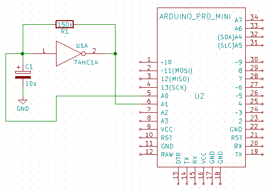
The Schmitt trigger works in such a way that the output voltage jumps at a moment when the voltage at the input exceeds a certain voltage. When voltage drops at the input, the output voltage stays stable until the voltage at the input drops below a certain voltage. This voltage is always significantly lower than the increase voltage, and this input property is called hysteresis. Thanks to it, the input is not sensitive to the noise.
Hysteresis will also serve us when creating an oscillator. Integrated circuit also causes signal negation. If the circuit is connected according to the diagram and we add the following components, it will oscillate:
- Capacitor between input and GND.
- Resistor between input and output.
It oscillates because when the power supply is connected to the integrated circuit, the voltage at input is similar to GND and the voltage at output is similar to VCC. Because the input and output are connected via a resistor, the current begins to flow through the resistor, which gradually charges the capacitor. The capacitor is charged at a defined voltage and at that moment the output is switched to a voltage similar to GND. The capacitor begins to discharge again through a resistor until the output voltage switches again.
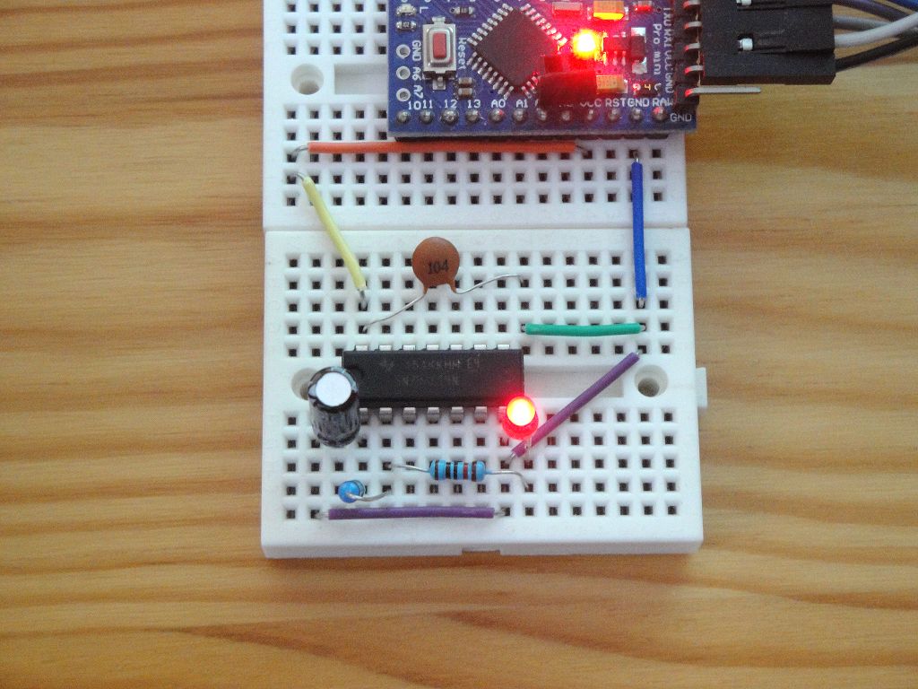
Input voltage varies between these two values. If we connect the LED with a resistor to the output, we can monitor the whole process well. Component values must be large enough to track the oscillation with the eyes. For example, if R = 150k and C = 10u the oscillation is approximately every second. The formula is approximately 1 / (R x C). An example of how to connect the integrated circuit on a breadboard can be found in the following image. The second capacitor in the image serves to block the voltage peaks and has a value of 0.1 uF.
I connected the Arduino to the circuit so we can visualize using analogue voltage measurement at checkpoints. Checkpoints are located at the input and at the output. The connection is on the following picture.
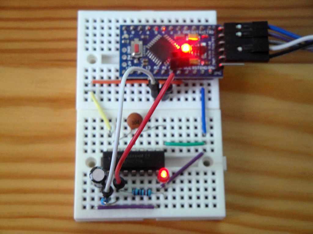
Arduino measures the voltage at pins A0 and A1 and sends the results to the serial port.
const double vref = 5.0;

void setup() {
  Serial.begin(9600);
}

void loop() {
  double a0 = analogRead(A0) * vref / 1023.0;
  double a1 = analogRead(A1) * vref / 1023.0;

  Serial.print(a0);
  Serial.print(",");
  Serial.print(a1);
  Serial.println("");
}
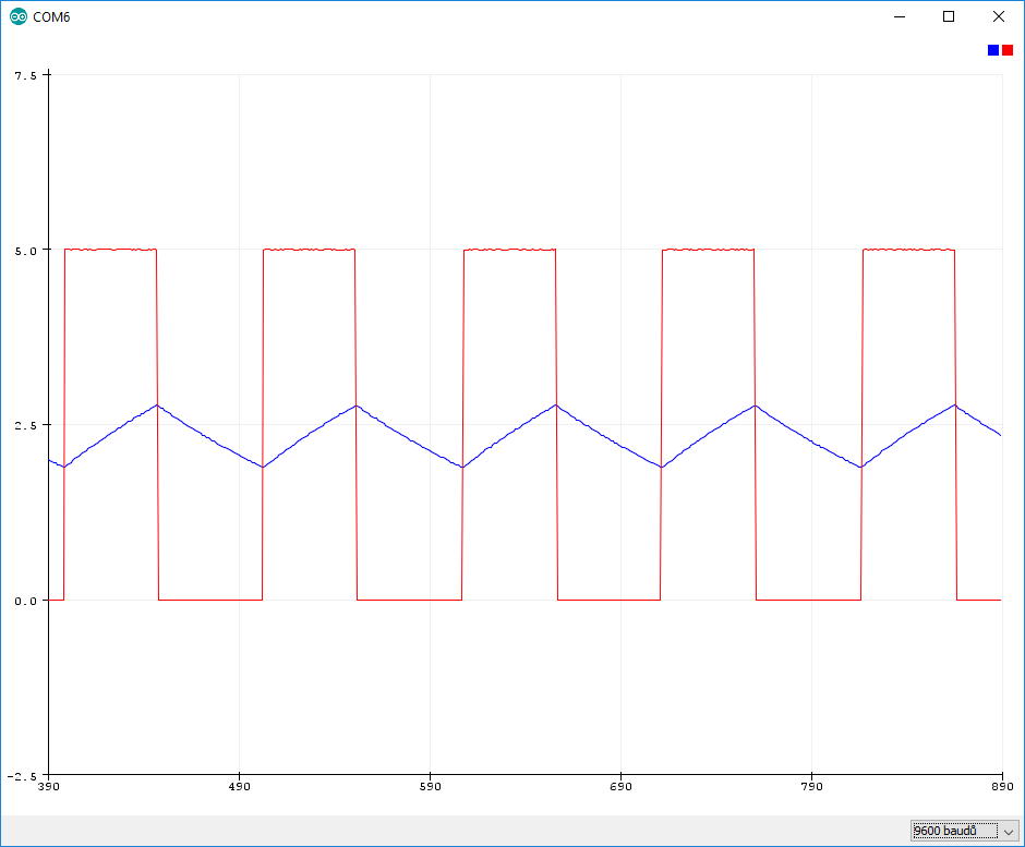
The measurement results can be visualized.
Source code
The source code is located on the GitHub server.
Video
07.01.2018