ATtiny85 - Buttons
Zápisník experimentátora
Hierarchy: ATtiny85
Buttons are simple parts that you can use to communicate with the microcontroller. Typically, microswitches are used, which can also be found in conventional consumer electronics. In today's article we will explain the basic use of the buttons and we will program a simple state machine in which we will have to make a button debounce.
How the button works
The button is a simple part. By pressing the button, the two conductors connect the path between them. In the ATtiny85 microcontroller pin we can see if there is a logical zero or unit on it. But if we just connected the button, one end to the pin and the other to the GNG or VCC, we would not be able to reliably differentiate if there is a defined voltage level on the button in the open state. Therefore, a pull-up is used, which will hold the button in the open state at the VCC level. In practice, instead of an external resistor, an internal pull-up resistor is used directly in the microcontroller.
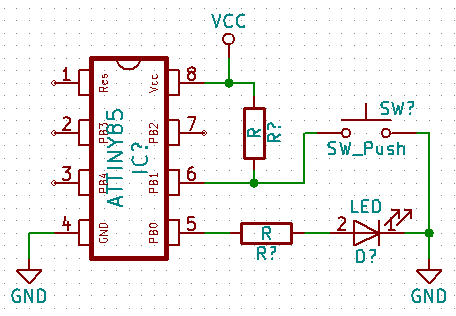
Because we have only internal pull-up resistors in the ATtiny85 microcontroller, we usually connect the button as shown in the diagram. The pressed button will indicate the logical zero and the unpressed button indicate logical one on the pin. The usual value for the resistor is 10k. If we use internal resistor, its value is about 50k. This value is not critical, and only in an exceptional case (for example, with an increased risk of interfering signals) a different value could be used.
Indication of key press by the LED
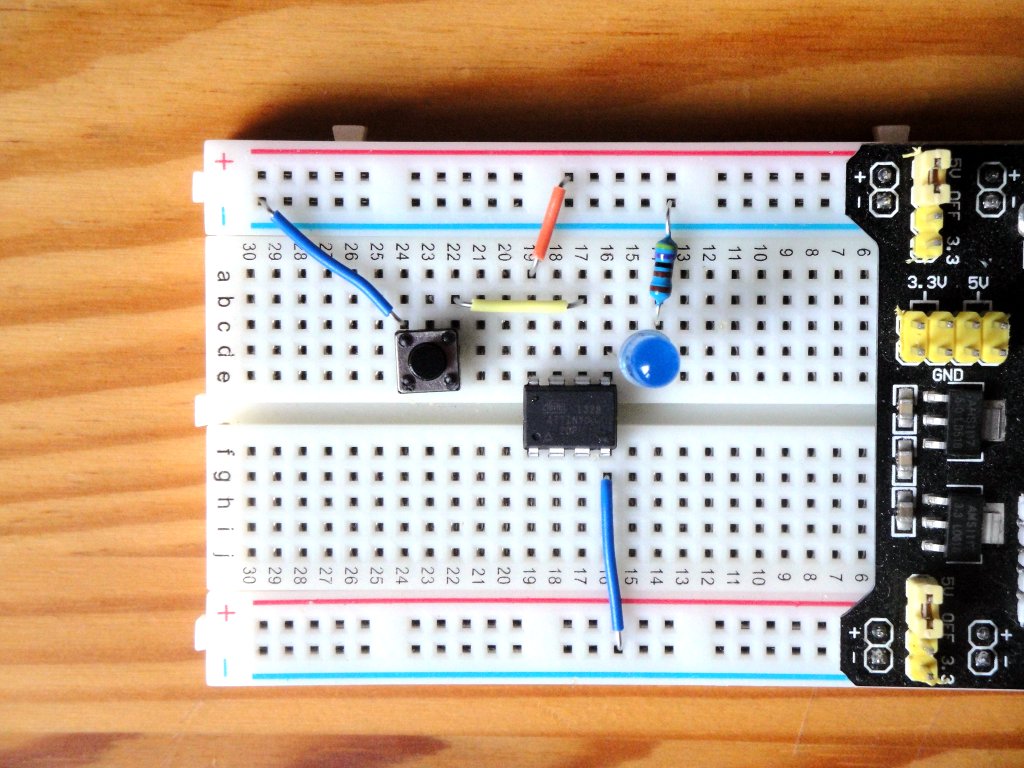
The simplest example is the LED on when you press the button. The connection is according to the attached diagram. The resistor at the pushbutton is 10k, the resistor at the LED is 1k. In order to read logical value on the pin, we need to define pin as an input using the function pinMode. Using the function digitaRead we read the logical value on the pin.
Because the push of a button is detected as a logical zero, we must negate the logic value so that the LED illuminates when the button is pressed. We could do this by using if and else, but for such simple tasks, it is also advisable to use a conditional ternary operator that evaluates the logical value of the first expression and results in a second or third expression. Source code button_state? LOW: HIGH means use LOW if button_state is true and HIGH if button_state is false.
const int led = 0;
const int button = 1;
int button_state = LOW;

void setup() {
  pinMode(led, OUTPUT);
  pinMode(button, INPUT);
}

void loop() {
  button_state = digitalRead(button);
  digitalWrite(led, button_state ? LOW : HIGH);
}
Internal pull-up resistor
I mentioned that we can also use an internal resistor to save one external resistor. The program is almost identical, only the second parameter into the function pinMode is INPUT_PULLUP. The connection is according to the first picture.
const int led = 0;
const int button = 1;
int button_state = LOW;

void setup() {
  pinMode(led, OUTPUT);
  pinMode(button, INPUT_PULLUP);
}

void loop() {
  button_state = digitalRead(button);
  digitalWrite(led, button_state ? LOW : HIGH);
}
One button ON / OFF
The second example we'll be dealing with is a state machine that will have two states. The first state is the LED off. The second state is an LED on.
I guess you'll think of a possible solution right away. You will monitor the status change on the pin and switch the state of the LED accordingly. But it has a minor problem. The contacts on the button do not work perfectly, and each switching on of the contacts is accompanied by minor bounces. During a few milliseconds, the contacts will be several tiemes connected and disconnected until they remain in the on-off state. The result will be switching the status of the LED, which sometimes responds correctly and sometimes not. It depends on how quickly your program can record the status change. And, the ATtiny85 microcontroller is able to quickly track the changes and switch the status of the LED several tiemes on 1 MHz. An example of such an unreliable program is in the following code.
const int led = 0;
const int button = 1;
int button_state = LOW;
int led_state = LOW;

void setup() {
  pinMode(led, OUTPUT);
  pinMode(button, INPUT_PULLUP);
}

void loop() {
  button_state = digitalRead(button);
  if(button_state == LOW)
    led_state = !led_state;
  digitalWrite(led, led_state);
}
The following code is used to correct this problem. After a detection of the first change of state is waiting a few milliseconds and if the change of state is still the same, it is considered as pressing the button.
const int led = 0;
const int button = 1;
int led_state = LOW;

// Button states and debounce
int buttonState = 0;
int lastButtonState = HIGH;
unsigned long lastDebounceTime = 0;

void setup() {
  pinMode(led, OUTPUT);
  pinMode(button, INPUT_PULLUP);
}

void loop() {
  int reading = digitalRead(button);
  if (reading != lastButtonState)
    lastDebounceTime = millis();

  if ((millis() - lastDebounceTime) > 50) {
    if (reading != buttonState) {
      buttonState = reading;
      if (buttonState == LOW) {
        led_state = !led_state;
      }
    }
  }

  lastButtonState = reading;

  digitalWrite(led, led_state);
}
If you only have one button, the previous code will work well. If you use multiple buttons, it is advisable to move the forwarding code to a separate class and use it as an object. You do not have to write this code yourself, and it is good if you go over an existing library. For example, the Bounce2 library will provide you with enough features to solve a variety of situations. The previous example will look like this using this library.
#include <Bounce2.h>

const int led = 0;
const int button = 1;
int led_state = LOW;

Bounce debouncer;

void setup() {
  pinMode(led, OUTPUT);
  pinMode(button, INPUT_PULLUP);
  debouncer.attach(button);
  debouncer.interval(5);
}

void loop() {
  debouncer.update();
  if (debouncer.fell())
    led_state = !led_state;

  digitalWrite(led, led_state);
}
Buttons and ATtiny85
In a few examples, we have shown how buttons are controlled by the ATtiny85 microcontroller. Examples are written universally, so they should work olso for Arduino.
Source code
The source code is located on the GitHub server.
- basic-button
- basic-button-pullup
- basic-button-nodebounce
- basic-button-debounce
- basic-button-debounce2
- Bounce2
26.02.2018