Simple development board for ATmega328P
Zápisník experimentátora
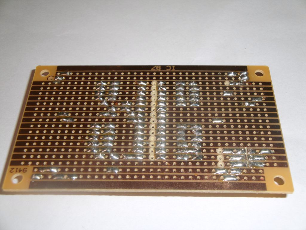
The simple development board for the ATmega328P microcontroller and its variants can be easily build on a universal printed circuit board. I've used a version called a stripboard. It is characterized by the fact that it has horizontal copper paths that fit the microcontroller pins. You do not need to solder many interconnecting wires that are replaced with copper paths. But you must break the paths in some places. For this, a drill to iron of a suitable size is used. The only problem with the ISP connector is that you need to cut the paths with a sharp knife directly between the pins.

An example of the scheme is in this image. The pin layout is retained by the pins on the microcontroller, so it does not exactly match the Arduino pins. The scheme corresponds to Arduino with 16 MHz crystal and LED on pin 13.
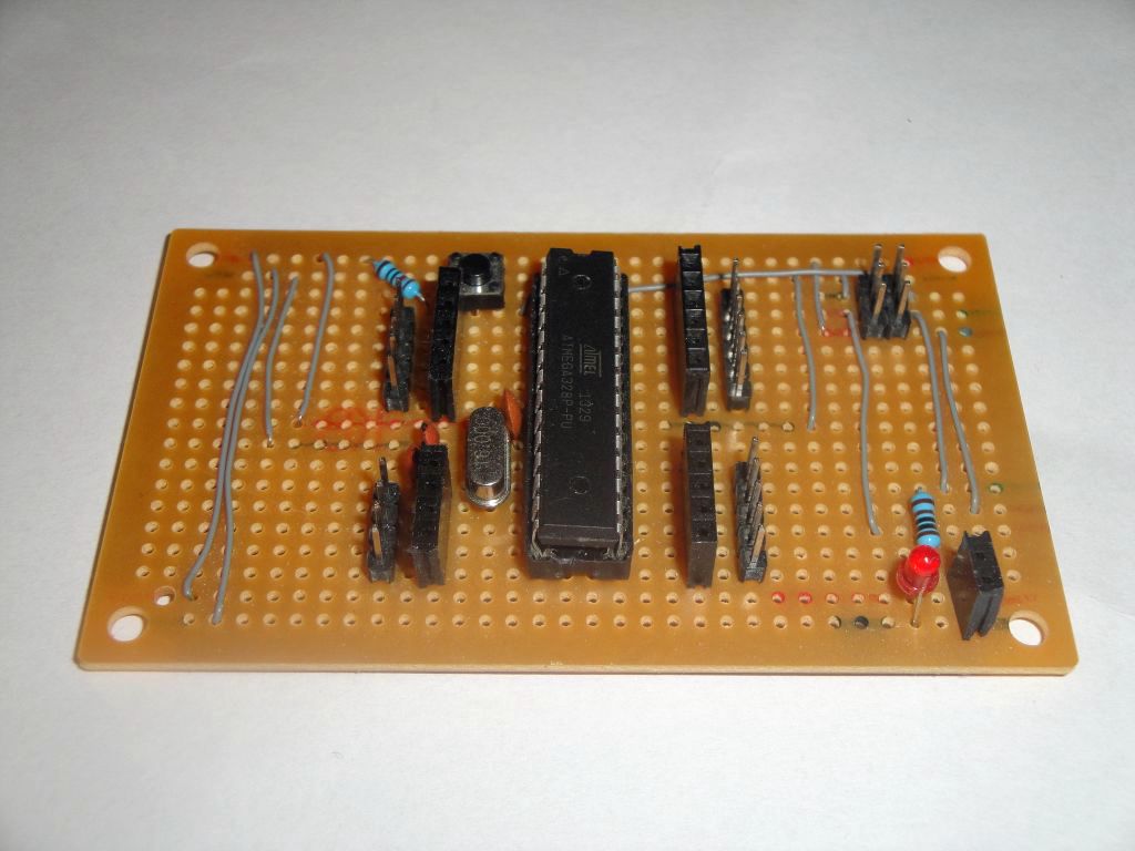
I used this board mostly for experiments with digital signals and therefore the involvement of the analogue part is not entirely ideal. On the diagram I draw it, but directly on the board is not the analog part involved. If you want to use it, you need to connect the AVCC and AREF pin. The proper connection of these pins can be found in the datasheet of the microcontroller.
The board can be used with MCUdude's MiniCore. In addition to the ATmega328P microcontroller, it can also be used for the ATmega8A microcontroller.
03.02.2018