Arduino and bipolar transistor as a switch
Zápisník experimentátora
In this article, we will explain how we can strengthen the Arduino output pin using a transistor. The purpose of the article is not to explain the theory of transistor operation. We will limit ourselves to the minimum necessary. As an example, we use a high-light LED, which can flow 350 mA. This is far beyond the possibilities of Arduino. We will be able to control it with a transistor.
Components
We need these parts.
- Breadboard {linkBreadboard}
- Resistor 100R, 10R, 1k {linkR}
- LED diode {linkLED}
- NPN Transistor BC547B {linkTransistor}
- OLED display {linkOLED}
- Wires
- Arduino {linkArduino}
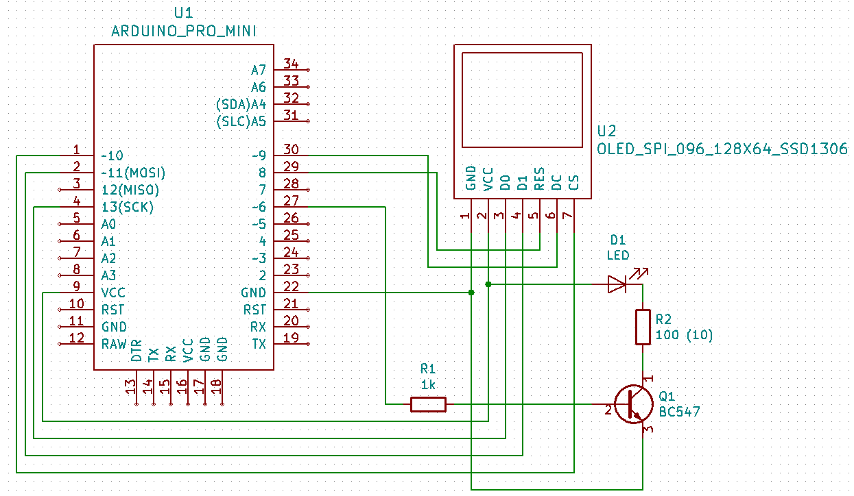
Bipolar transistor
The bipolar transistor works by connecting the Arduino output pin to the transistor base. You must limit the overcurrent by using a resistor. Since the BC547B resistor used has an amplification factor of approximately 200, a 1k resistor can be used. If you would like to calculate a value, you can do so using a simple formula. The open transistor voltage between the base and emitter is approximately 0.7V. To make sure the transistor opens, we'll use three times what we need to be sure.
(5V - 0,7V) / 1000 * 200 / 3 = 0.28A
Small wiring note. We should connect one more 100k R3 resistor to the transistor base. Nothing bad happens when you engage on a breadboard. However, Arduino has its outputs when connected to a power supply in high impedance. This means that they are not connected to either VCC or GND. They're like in the air. And because it is enough to bring a small current to the base to turn the transistor on, it may happen that the diode lights up for a while before the Arduino sketch starts.
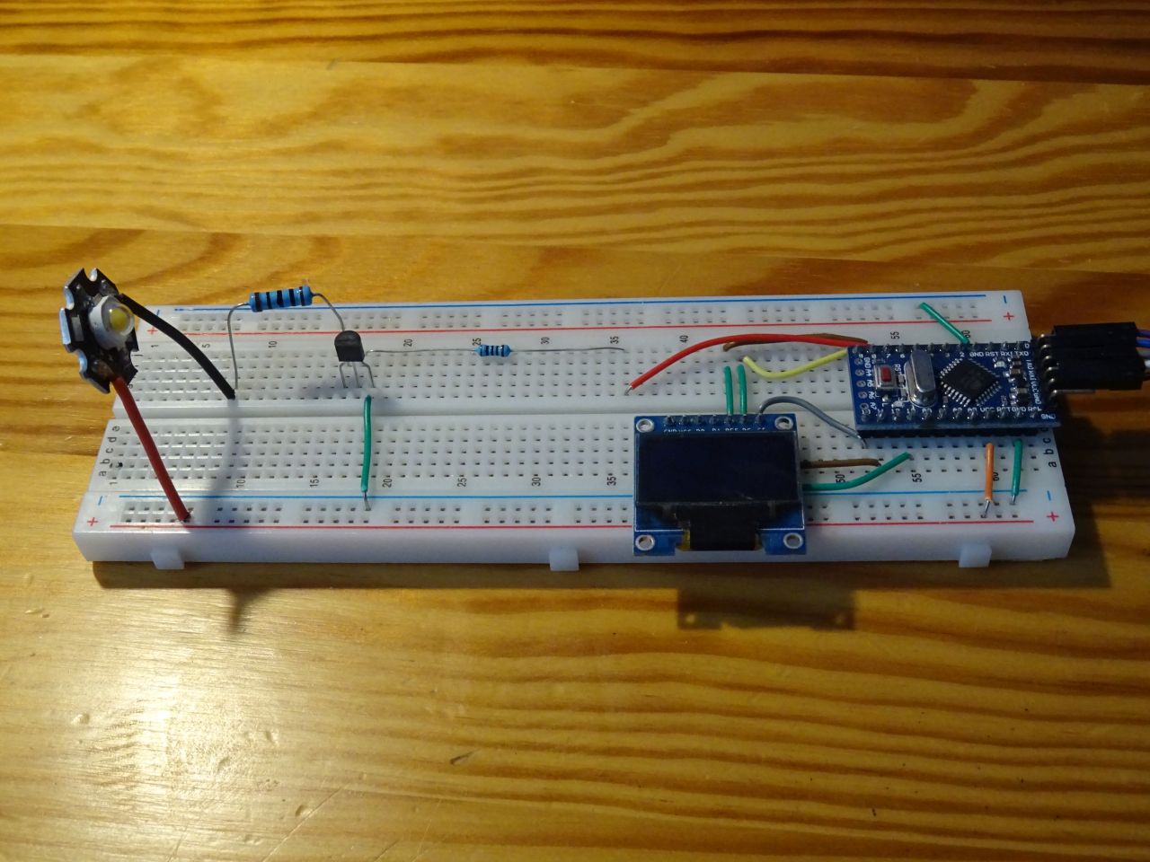
Program
I also used OLED display. In this particular case of LED flashing is not necessary, but I am already preparing the material for the following article. In this case, the display only shows the current status based on the transistor. In the program I use the TimerOne library to flash the LEDs at half-second intervals.
#include <U8g2lib.h>
#include <TimerOne.h>

U8G2_SSD1306_128X64_NONAME_1_4W_HW_SPI u8g2(U8G2_R0, /* cs=*/ 10, /* dc=*/ 9, /* reset=*/ 8);

#define ledPin 6
int ledState = LOW;

void setup() {
  u8g2.begin();
  u8g2.setFont(u8g2_font_ncenB10_tr);

  pinMode(ledPin, OUTPUT);
  Timer1.initialize(500000); // 500 ms
  Timer1.attachInterrupt(blinkLed);
}

void loop() {
  for (int i = 12; i < 64 - 24; i++) {
    drawFrame(i);
    delay(10);
  }
  for (int i = 63 - 24; i >= 12; i--) {
    drawFrame(i);
    delay(10);
  }
}

void drawFrame(int y) {
  u8g2.firstPage();
  do {

  u8g2.drawStr(0, y, "Arduino Slovakia");
  u8g2.drawStr(8, y + 12, "Blink");
  u8g2.drawStr(8, y + 24, ledState ? "ON" : "OFF");
  for (int j = 0; j <= 128; j += 2)
    u8g2.drawLine(j, 0, j, (j % 10 == 0 ? 2 : 1));
  for (int j = 0; j <= 64; j += 2)
    u8g2.drawLine(0, j, (j % 10 == 0 ? 2 : 1), j);

  } while ( u8g2.nextPage() );
}

void blinkLed(){
  ledState = !ledState;
  digitalWrite(ledPin, ledState);
}
Source code
The source code is located on the GitHub server.
01.03.2020