LED dimmer with timer
Zápisník experimentátora
Hierarchy: Časovač (timer)
The dimming of LED can be programmed in several ways. In this article, we will focus on not having a function delay in the program that hinders the running of the program so that it can no longer do anything else. Nor will we use the function millis to eliminate program delays. Instead, we will use the timer, which we set to give us a signal at regular intervals when we should do the next dimming step.
We will use my online calculator to calculate the register settings for the CTC timer in the ATmega328P microcontroller, located in Arduino. The timer will call an interrupt every 1 ms and from this basic step we will deduce by simple calculation larger steps that will set the PWM signal on the output pin.
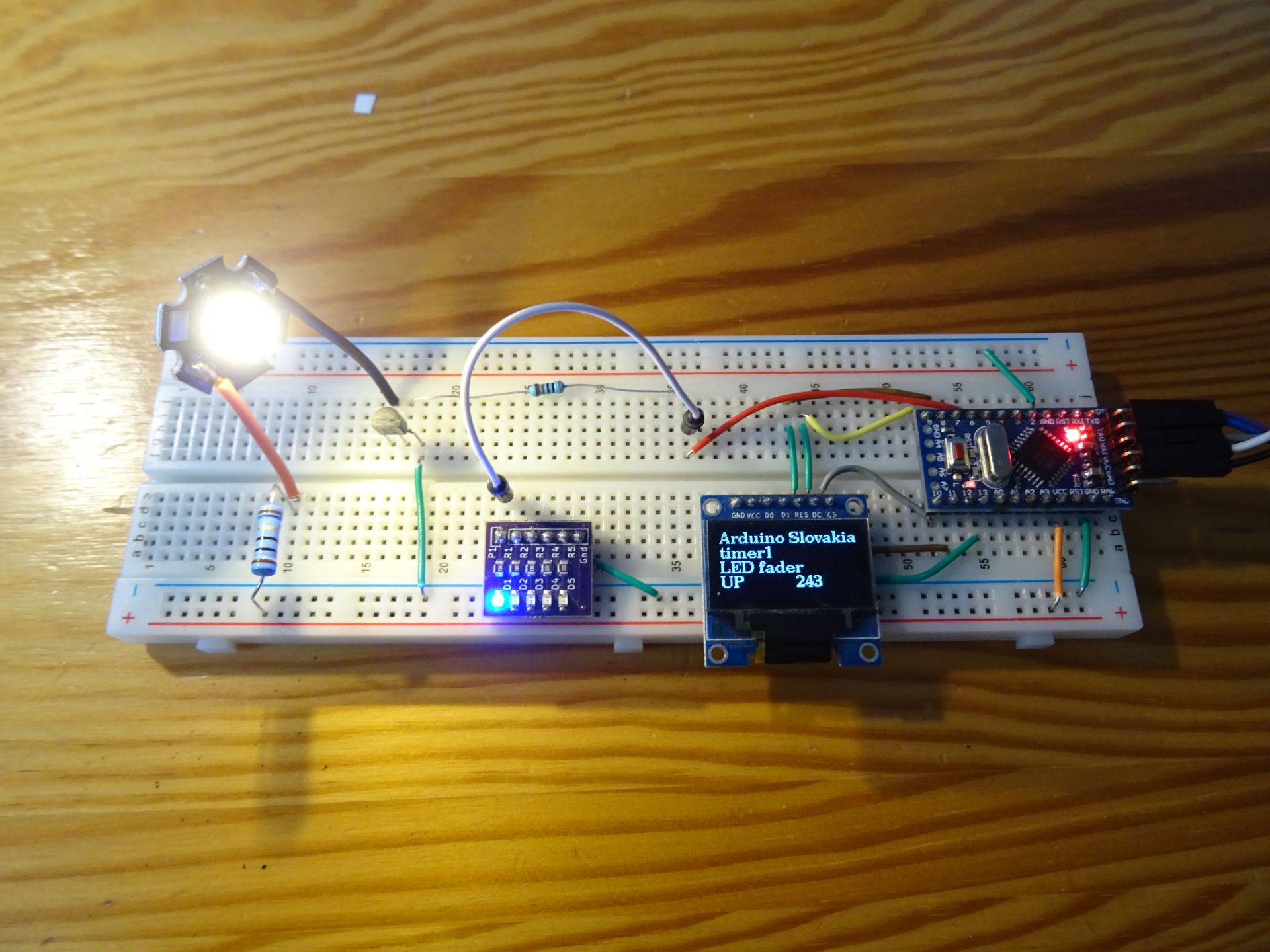
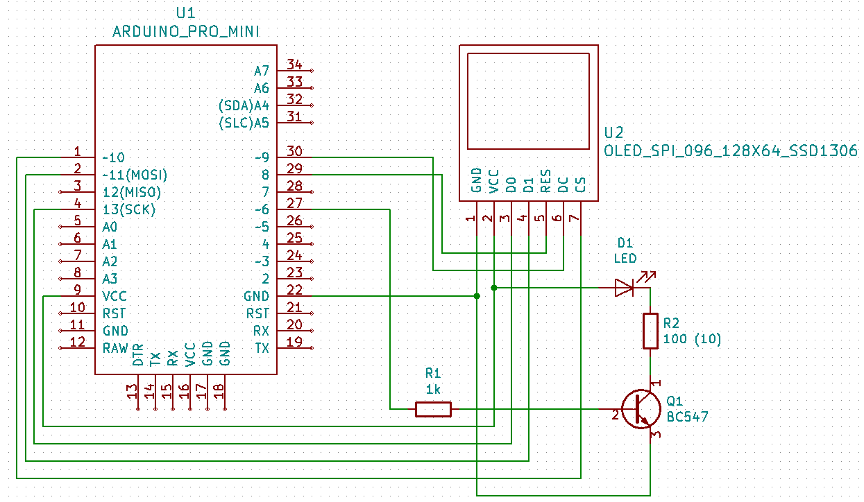
In this article we will use the electrical circuit from the previous article on NPN transistor. The base of the transistor is connected to pin 6, which can also be controlled by PWM signal. This way we can test that the PWM signal can also control electrical circuits that cannot be directly connected to the Arduino output pin. The diagram also includes an OLED display. We do not need this for the experiment, but it will allow us to demonstrate that the program is not waiting for anything and so we can write the information on the OLED display in the function loop.
However, if you do not have a transistor, power led or OLED display, you can omit all of these components. Just connect pin 6 with resistor and LED and try the program in this form. I wrote two programs. One is usable for such a basic wiring and the other is usable with a power LED and OLED display.
Components
We need these parts.
- Breadboard {linkBreadboard}
- Resistor 100R, 10R, 1k {linkR}
- LED diode {linkLED}
- NPN Transistor BC547B {linkTransistor}
- OLED display {linkOLED}
- Wires
- Arduino {linkArduino}
Basic program
The timer calls an interrupt every millisecond. If we were to animate the LED dimming this fast, it would be too fast. Therefore, I have defined that one step is performed only once in 10 ms (timerStep). This plays the entire animation in 2550 ms. PWM (pwmvalue) is animated first from 0-255 (direction) and then from 255-0. This gives the impression that the LED is breathing. It lights up and goes off smoothly. Notice the loop function. Does not contain any code.
#define ledPin 6
#define timerStep 10

volatile int divider = 0;
volatile int pwmvalue = 0;
volatile int direction = 1;

void setupTimer1() {
  noInterrupts();
  // Clear registers
  TCCR1A = 0;
  TCCR1B = 0;
  TCNT1 = 0;

  // 1000 Hz (16000000/((249+1)*64))
  OCR1A = 249;
  // CTC
  TCCR1B |= (1 << WGM12);
  // Prescaler 64
  TCCR1B |= (1 << CS11) | (1 << CS10);
  // Output Compare Match A Interrupt Enable
  TIMSK1 |= (1 << OCIE1A);
  interrupts();
}

void setup() {
  pinMode(ledPin, OUTPUT);
  setupTimer1();
}

void loop() {
}

void pwmStep() {
  analogWrite(ledPin, pwmvalue);
  pwmvalue += direction;
  if (pwmvalue == 0)
    direction = 1;
  if (pwmvalue == 255)
    direction = -1;
}

ISR(TIMER1_COMPA_vect) {
  if (divider == 0)
    pwmStep();
  divider++;
  divider %= timerStep;
}
Program with OLED display
In this program, the dimming code is the same as in the previous example. I added OLED display. It shows the current values of the variables. I use the loop function to draw information on the display. Notice the interesting macro ATOMIC_BLOCK. This ensures the atomicity of the variables, since interrupt can occur at any time during the main code. The macro ensures that local copies of some variables can be made, the value of which is displayed on the display.
#include <U8g2lib.h>
#include <util/atomic.h>

U8G2_SSD1306_128X64_NONAME_1_4W_HW_SPI u8g2(U8G2_R0, /* cs=*/ 10, /* dc=*/ 9, /* reset=*/ 8);

#define ledPin 6
#define timerStep 10

volatile int divider = 0;
volatile int pwmvalue = 0;
volatile int direction = 1;

void setupTimer1() {
  noInterrupts();
  // Clear registers
  TCCR1A = 0;
  TCCR1B = 0;
  TCNT1 = 0;

  // 1000 Hz (16000000/((249+1)*64))
  OCR1A = 249;
  // CTC
  TCCR1B |= (1 << WGM12);
  // Prescaler 64
  TCCR1B |= (1 << CS11) | (1 << CS10);
  // Output Compare Match A Interrupt Enable
  TIMSK1 |= (1 << OCIE1A);
  interrupts();
}

void setup() {
  u8g2.begin();
  u8g2.setFont(u8g2_font_ncenB10_tr);

  pinMode(ledPin, OUTPUT);
  setupTimer1();
}

void drawLogo() {
  int y = 12;
  int stp = 14;
  int cpwmvalue;
  int cdirection;
  char prt[10];
  ATOMIC_BLOCK(ATOMIC_RESTORESTATE) {
    cpwmvalue = pwmvalue;
    cdirection = direction;
  }
  u8g2.firstPage();
  do {

  u8g2.drawStr(0, y, "Arduino Slovakia");
  u8g2.drawStr(0, y + stp * 1, "timer1");
  u8g2.drawStr(0, y + stp * 2, "LED fader");
  u8g2.drawStr(0, y + stp * 3, cdirection==1 ? "UP" : "DOWN");
  sprintf(prt, "%d", cpwmvalue);
  u8g2.drawStr(70, y + stp * 3, prt);
  } while ( u8g2.nextPage() );
}

void loop() {
  drawLogo();
}

void pwmStep() {
  analogWrite(ledPin, pwmvalue);
  pwmvalue += direction;
  if (pwmvalue == 0)
    direction = 1;
  if (pwmvalue == 255)
    direction = -1;
}

ISR(TIMER1_COMPA_vect) {
  if (divider == 0)
    pwmStep();
  divider++;
  divider %= timerStep;
}
Source code
The source code is located on the GitHub server.
Video
21.03.2020