How to use an external EEPROM
Zápisník experimentátora
Hierarchy: Externá EEPROM
This article explains how we can work with an external EEPROM. External EEPROMs are usually controlled by the I2C protocol and this article will deal with just such an EEPROM. The example will be for 24LC16B, but this tutorial will be universal for any EEPROM.
Used components
For this experiment you only need a few components:
- Arduino Pro Mini (link) - I used it because it will fit into the smallest breadboard.
- Breadboard 400 Holes (link) - On it we have enough space for the two microswitches.
- Converter CP2102 USB to Serial (link) - The converter is used to program the Arduino.
- Microswitches (link, link) - We need two pieces. Four and two pins can also be used in the breadboard. Sometimes the pins are longer, or they have strange protrusions. Do not be afraid to cut those ends in order to get stuck.
- EEPROM 24LC16B
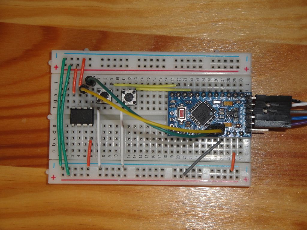
The Arduino is designed to have an I2C (extraordinary extra pins in the middle of Arduino) with a pin header to make it easy to connect with the EEPROM via two connecting wires.
The two buttons are used to run specific tests and are connected to pins 6 and 8 on Arduino. The EEPROM is connected to the power supply and the address pins A0, A1 and A2 are not connected. This only applies to this particular type of EEPROM. Others usually have to connect these pins to GND or VCC to set the I2C address. You should always check the datasheet for the specific type and set it according to it.
Libraries
There is a good extEEPROM library for EEPROM control. Install it through library manager.
Example
When I was creating this example, I came out of what is attached to the library. At the time of writing this article, an example with errors was attached. So use my example.
The example lists the contents of the EEPROM and waits for the button to be pressed. Two buttons can cause the following action:
- Button 6 - Writing test. The test fills the entire memory incrementally with increasing 32-bit numbers. It then lists the contents of the entire memory.
- Button 8 - Erasing test. The test fills the entire memory with 0xff. It then writes the contents of the entire memory.
I will not comment on the entire source code, only its essential parts. The eeErase, eeWrite, and eeRead functions have only slightly changed against the original and are found only in complete source texts.
External EEPROM 24LC16B can store 2K of 8-bit values. In this case, it represents the eep object. It took me a while to guess the source text for what the page size parameter is. For you, it's important to know that there's always a value of 16. It's the amount of data that can be transferred at a time, and the size is also limited by the Arduino implementation of I2C.
#include <extEEPROM.h>

//One 24LC16B EEPROMs on the bus
const uint32_t totalKBytes = 2; // for read and write test functions
const uint8_t chunkSize = 4;    // this can be changed, but must be a multiple of 4 since we're writing 32-bit integers
extEEPROM eep(kbits_16, 1, 16); // device size, number of devices, page size

const uint8_t btnStart = 6;     // start button
const uint8_t btnErase = 8;     // erase button
In the setup function, I set two buttons as inputs and I do not have to give external resistors on the test field; internal pull-up resistors are activated here. This means that we only measure the LOW on the given pin when the microswitch is depressed. The serial port is set to 115200 to make the data listings fast. After resetting Arduino, the current EEPROM content and function list legend will be displayed.
void setup(void)
{
  pinMode(btnStart, INPUT_PULLUP);
  pinMode(btnErase, INPUT_PULLUP);
  Serial.begin(115200);
  uint8_t eepStatus = eep.begin(twiClock400kHz);      //go fast!
  if(eepStatus) {
    Serial.print(F("extEEPROM.begin() failed, status = "));
    Serial.println(eepStatus);
    while (1);
  }

  // dump current EEPROM memory
  dump(0,totalKBytes*1024);

  Serial.println(F(""));
  Serial.println(F("Press button '6' to start write test"));
  Serial.println(F("Press button '8' to start erase test"));
}
The loop function monitors whether or not we have pressed a button. A short delay is used to handle debouncing, but it takes longer in real time to write and list data, so there might not be a function call there.
void loop(void)
{
if(digitalRead(btnStart) == LOW) {
  delay(100);
  eeWrite(chunkSize);
  eeRead(chunkSize);
  dump(0,totalKBytes*1024);
  }

if(digitalRead(btnErase) == LOW) {
  delay(100);
  eeErase(chunkSize,0,totalKBytes*1024);
  dump(0,totalKBytes*1024);
  }
}
The dump function serves as a checklist of data. I did not write it, but inside I fixed bugs to prevent the content of the memory being formatted. I like how the author attempted to format the data clearly. Try to guess what it looks like in the code.
void dump(uint32_t startAddr, uint32_t nBytes)
{
  Serial.print(F("EEPROM DUMP 0x"));
  Serial.print(startAddr, HEX);
  Serial.print(F(" 0x"));
  Serial.print(nBytes, HEX);
  Serial.print(F(" "));
  Serial.print(startAddr);
  Serial.print(F(" "));
  Serial.println(nBytes);
  uint32_t nRows = (nBytes + 15) >> 4;

  uint8_t d[16];
  for(uint32_t r = 0; r < nRows; r++) {
    uint32_t a = startAddr + 16 * r;
    eep.read(a, d, 16);

    Serial.print(F("0x"));
    if ( a < 16 * 16 * 16 ) Serial.print(F("0"));
    if ( a < 16 * 16 ) Serial.print(F("0"));
    if ( a < 16 ) Serial.print(F("0"));
    Serial.print(a, HEX); Serial.print(F(" "));

    for(int c = 0; c < 16; c++) {
      if(d[c] < 16)
        Serial.print(F("0"));
      Serial.print(d[c], HEX);
      Serial.print(c == 7 ? "  " : " ");
    }
    Serial.println(F(""));
  }
}
If you do not have time or you read an article out of curiosity and you will not build the circuit, then the function output looks like this.
EPROM DUMP 0x0 0x800 0 2048
0x0000 00 00 00 00 00 00 00 01  00 00 00 02 00 00 00 03
0x0010 00 00 00 04 00 00 00 05  00 00 00 06 00 00 00 07
0x0020 00 00 00 08 00 00 00 09  00 00 00 0A 00 00 00 0B
0x0030 00 00 00 0C 00 00 00 0D  00 00 00 0E 00 00 00 0F
This was a brief introduction to using external EEPROMs. In one of the following articles, we'll look at the data from a practical page and show you how to store more complex data comfortably and safely.
Source code
The source code is located on GitHub.
09.08.2017