CTC timer in ATtiny85 microcontroller
Zápisník experimentátora
Hierarchy: Časovač (timer)
ATtiny85 contains two 8-bit timers. They do not have the same range as those in ATmega328P, but it is enough for most tasks. In this article, we look at timers from CTC mode. We will use the online calculator to generate the programs.
Used parts
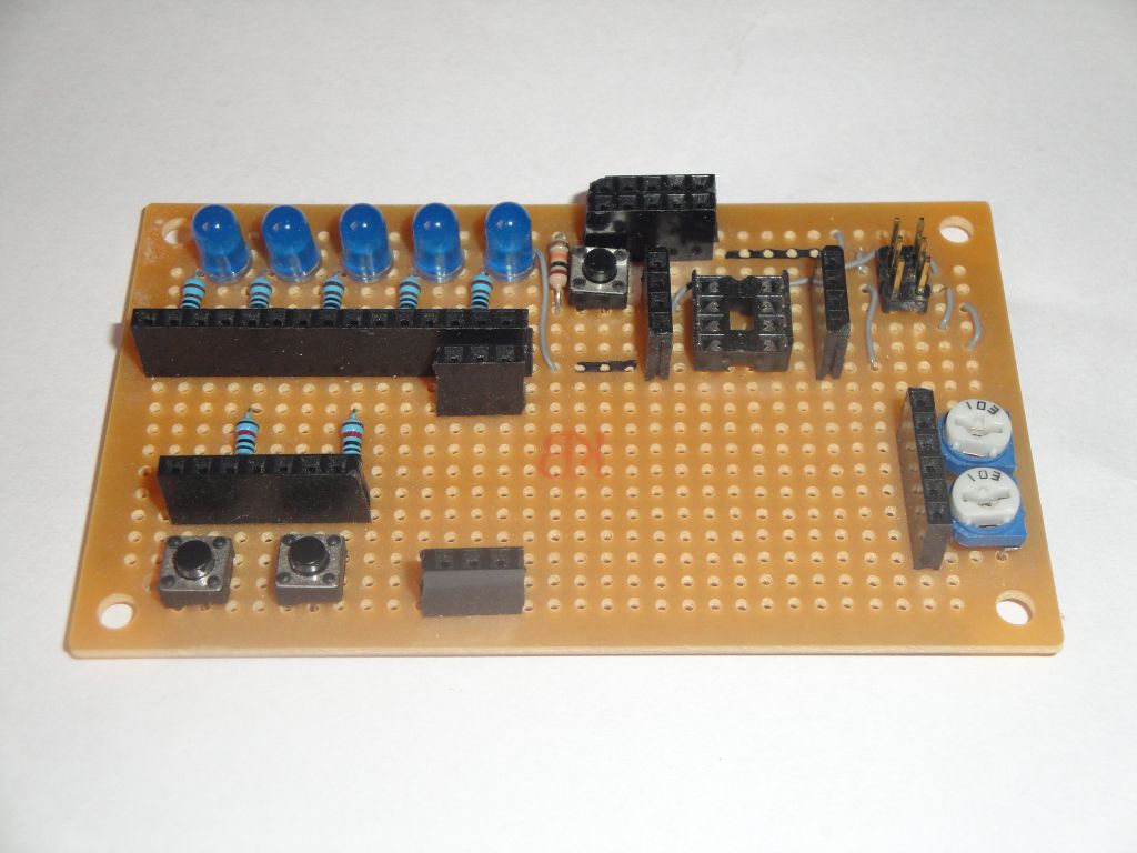
If you want to try out experiments, you will need.
- A development board for ATtiny85, or a breadboard with a microcontroller.
- USBasp programmer.
I wrote the source codes for frequencies of 1000000, 8000000 and 16000000. I used the kernel https://github.com/SpenceKonde/ATTinyCore. There are three examples for each timer. They all flash with an LED that is connected to pin 0. Pin 0 is on the microcontroller at the bottom right.
Timer0
Timer0 is basically identical to the same timer in ATmega328P. That's why the registry setting looks pretty much the same. What may be different is the location of the individual bits, but because we use my calculator, we do not have to worry about it. Because we are working at a low frequency of 1 Hz, we can not set it to timer directly. I use a small trick and set the frequency to 100 Hz and in the interrupt handler I use the modulo to divide this frequency by 100 and I get to the required 1 Hz. The calculator already has a template that generates this code.
#define ledPin 0
volatile int divider=0;

void setupTimer0() {
  noInterrupts();
  // Clear registers
  TCCR0A = 0;
  TCCR0B = 0;
  TCNT0 = 0;

  // 100.16025641025641 Hz (1000000/((155+1)*64))
  OCR0A = 155;
  // CTC
  TCCR0A |= (1 << WGM01);
  // Prescaler 64
  TCCR0B |= (1 << CS01) | (1 << CS00);
  // Output Compare Match A Interrupt Enable
  TIMSK |= (1 << OCIE0A);
  interrupts();
}

void setup() {
  pinMode(ledPin, OUTPUT);
  setupTimer0();
}

void loop() {
}

ISR(TIMER0_COMPA_vect) {
  if(divider==0)
    digitalWrite(ledPin, digitalRead(ledPin) ^ 1);
  divider++;
  divider%=100;
}
Timer1
Timer1 is more complicated in CTC mode. It is set differently and we need to set multiple registers. On the other hand, however, we have much more divisions available, which gives the timer better possibilities.
Note that we need to set two registers to set the desired frequency. This timer sets the frequency with one register and causes interrupt by another. In my case, both registers have the same value. However, the OCR1A value can have any value, but it must not be larger than the value in OCR1C. In this case, we do not care when exactly the interruption occurs, it is enough for us to come and call our interrupt with processing code. But this seemed to me be clearer and so I set it up in the calculator.
#define ledPin 0
volatile int divider=0;

void setupTimer1() {
  noInterrupts();
  // Clear registers
  TCNT1 = 0;
  TCCR1 = 0;

  // 100.16025641025641 Hz (1000000/((155+1)*64))
  OCR1C = 155;
  // interrupt COMPA
  OCR1A = OCR1C;
  // CTC
  TCCR1 |= (1 << CTC1);
  // Prescaler 64
  TCCR1 |= (1 << CS12) | (1 << CS11) | (1 << CS10);
  // Output Compare Match A Interrupt Enable
  TIMSK |= (1 << OCIE1A);
  interrupts();
}

void setup() {
  pinMode(ledPin, OUTPUT);
  setupTimer1();
}

void loop() {
}

ISR(TIMER1_COMPA_vect) {
  if(divider==0)
    digitalWrite(ledPin, digitalRead(ledPin) ^ 1);
  divider++;
  divider%=100;
}
Source code
The source codes are located on the GitHub server.
31.10.2017