ATtiny85 and supercapacitor
Zápisník experimentátora
Hierarchy: ATtiny85
I tested a small 1.5 F capacitor together with ATtiny85 microcontroller. It is manufactured by Panasonic and operates at a maximum voltage of 5.5 V. The capacitor is designed for back-up of low-energy devices. I used the ATtiny85 microcontroller at 1 MHz to comply with the condition of the low-power device. Do you want to know how long the microcontroller worked?

Components
I used these components.
- EECS5R5H155 - Capacitor Panasonic 1,5 F/5,5 V.
- ATtiny85 - Microcontroller.
- Mini breadboard (link) - It has a sufficient number of holes for the entire project.
- 3x red LED - The voltage drop is approximately 1.8 volts.
- 3x 1k resistor - The resistor sets the current through the LED to approximately 1 mA.
- Wire jumpers (link) - By using them, the resulting breadboard connection looks very nice.
- B3603 (link) - The constant current source I used to charge the capacitor.
Supercapacitor
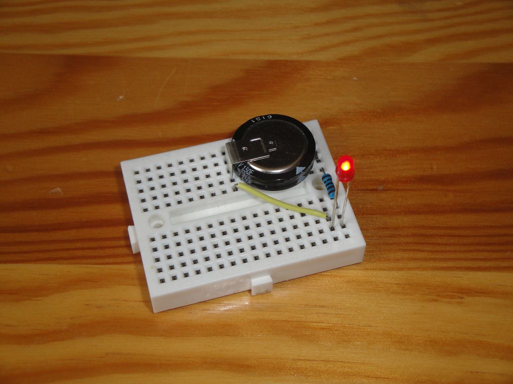
In the documentation, it can be found that the maximum discharge current should be 1 mA. Charging current not listed. I charged supercapacitor with a constant current source I've set at the B3603. I set the current of 20 mA and 5 volts and after a few minutes the capacitor was charged. I tested one red LED and a 1k resistor. As expected, the entire circuit turned on for more than an hour until the capacitor dropped to 1.6V when the LED went out. I did not follow it exactly, but it took at least an hour.
ATtiny85
I used this microcontroller because it can easily be set to a 1 MHz frequency at which it has low power consumption. At the pins PB0, PB1 and PB2 I connected LED and resistor 1k. The Arduino IDEs are pins 0, 1 and 2. ATTinyCore is used as the core. I programmed it via USBAsp. I have my own development board for programming. In it I programmed the microcontroller, tested it and then I moved it to the breadboard and connected as shown.
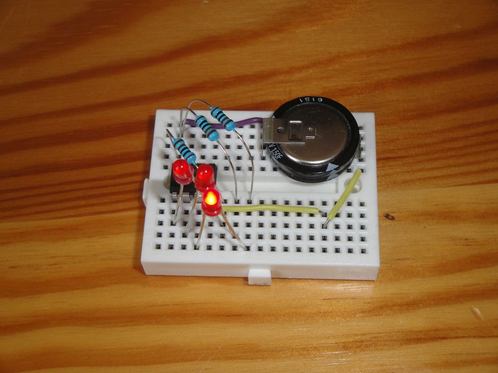
Table of measured voltages on the condenser at 10 minutes. Thus, the capacitor gradually discharged. The ATtiny85 documentation states that it is capable of operating at a voltage of 1.8 V. This is already on the limit of the red LED capability. Here are a few guideline figures to get you an idea of how the condenser is gradually discharged. The capacitor showed a voltage of 4.77 V just after charging. The current was measured badly, because the flashing diodes changed slightly, so it's my estimate of the data that the multimeter showed me.
| Time | Voltage | Current |
|---|---|---|
| 00:00 | 4,61 V | 2-3 mA |
| 00:10 | 3,75 V | 1,4-2 mA |
| 00:20 | 3,10 V | 1-1,6 mA |
| 00:30 | 2,66 V | 0,8-1,2 mA |
| 00:40 | 2,29 V | 0,7-0,9 mA |
| 00:50 | 1,96 V | |
| 01:00 | 1,68 V | |
| 01:05 | 1,57 V | I was no longer able to detect LED flashes. By measuring the pins I found that the microcontroller is still working. |
| 01:10 | 1,45 V | |
| 01:20 | 1,30 V | Here I had to stop measuring. But the microcontroller was still working. |
It is clear from the measurements that even without any effort to reduce consumption, the microcontroller has been working for a very long time. Switching the microcontroller to the sleep can save a lot of energy. Sometimes we can try out how many hours the microcontroller could handle in sleep mode.
Video
Video is located on the YouTube server.
Source code
I used the source code from the aircraft model lighting using 3W LEDs. The source code is located on the GitHub server.
27.08.2017