ATtiny85 Piranha LED Lamp
Zápisník experimentátora
Hierarchy: ATtiny85
The birth of the second child was an inspiration for this project. We needed a highly portable source of light to which it is possible to smoothly adjust the brightness. I took advantage of the Bambíno and ATtiny13A project and created a LED light project that is powered by a 4.5 V battery. This LED light is controlled by ATtiny85 microcontroller, but the program is also compatible with ATtiny13A.
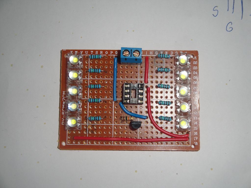
In the picture is a universal PCB. There are 10 Piranha LEDs along with series resistors. All LEDs are connected in parallel to the 2N7000 MOSFET, whose gate is controlled by a microcontroller. This allows you to continuously adjust the brightness using PWM from a microcontroller. The brightness is set by a potentiometer that is not on the printed circuit board. The potentiometer must be placed in the wall of the box that encapsulates the printed circuit board. We use redundant plastic jars for food at home, but also a plastic box with a transparent wall can be used.

Diagram of the entire circuit is in this picture. You see, it is all very simple. There is no need to put a resistor on the Mosfet Gate because the 2N7000 needs only a tiny electrical charge to open. However, there is a need for resistor R2, which will hold as a pull-down gate during the start of the microcontroller, when the pin PB0 is high impedance and could accidentally fade even when the finger is touched. The LED is connected via a series resistor that adjusts the current through the LED to 11-13 mA. This depends on the battery voltage. I used a flat battery with a voltage of 4.5 V that left my previous project.
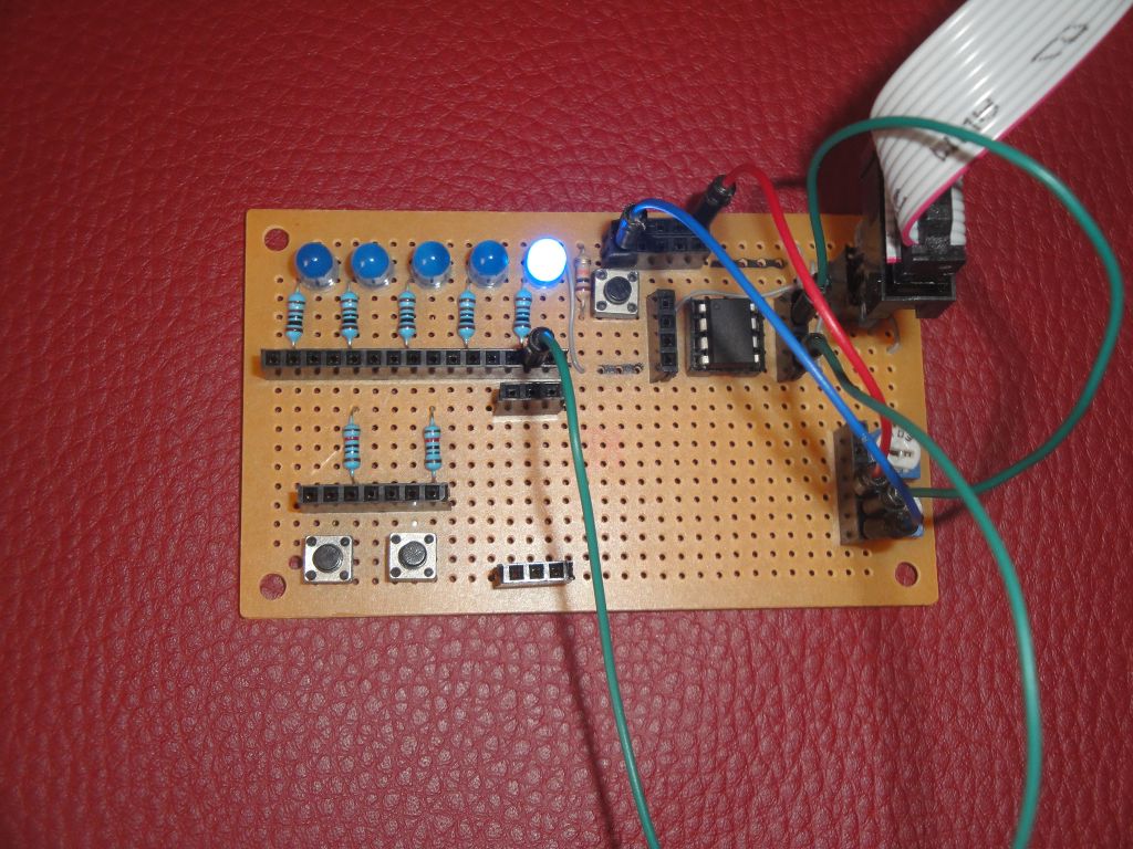
In this picture is ATtiny85 on the development board. LED diode and potentiometer are connected. The development board enables programming of the microcontroller via USBasp.

This figure shows the back of the universal printed circuit board. The Piranha LEDs have four pins. This allows them to easily soldered into rows next to each other. You can find the meaning of each pin via a multimeter. Always two pins are connected to the anode and cathode of the LED.

This figure shows the used parts.
- Universal printed circuit board
- Potentimeter 100k
- 10x resistor 150R
- 10x LED diode Piranha
- 1x Mosfet 1N7000 (there are two in the picture, but one is enough)
- 8-pin socket for ATtiny85

This is a preview of testing using a constant current source. I use the B3603. The current is set to 1 mA. Note where the connecting wires are connected during the test. The VCC is connected to pin 8 and GND to pin 4. In addition, the pin 8 and 5 are connected together, which simulates the HIGH signal at gate Mosfet.
The sketch
The program is just a minor modification to my older program. On pin PB2 it measures the voltage from the potentiometer and according to it sets the PWM signal to pin PB0. The PWM signal is adapted to the human eye.
const int led = 0;
const int pot = A1;
int pot_value = 0;

// ATMEL ATTINY85
//
//                  +-\/-+
//      (D 5) PB5  1|    |8  Vcc
//      (D 3) PB3  2|    |7  PB2 (D 2) pot
//      (D 4) PB4  3|    |6  PB1 (D 1)
//            GND  4|    |5  PB0 (D 0) led
//                  +----+

// table of exponential values
// generated for values of i from 0 to 255 -> x=round( pow( 2.0, i/32.0) - 1);
const byte table[] PROGMEM = {
  0,   0,   0,   0,   0,   0,   0,   0,   0,   0,   0,   0,   0,   0,   0,   0,
  0,   0,   0,   1,   1,   1,   1,   1,   1,   1,   1,   1,   1,   1,   1,   1,
  1,   1,   1,   1,   1,   1,   1,   1,   1,   1,   1,   2,   2,   2,   2,   2,
  2,   2,   2,   2,   2,   2,   2,   2,   2,   2,   3,   3,   3,   3,   3,   3,
  3,   3,   3,   3,   3,   3,   4,   4,   4,   4,   4,   4,   4,   4,   4,   5,
  5,   5,   5,   5,   5,   5,   5,   6,   6,   6,   6,   6,   6,   6,   7,   7,
  7,   7,   7,   8,   8,   8,   8,   8,   9,   9,   9,   9,   9,  10,  10,  10,
 10,  11,  11,  11,  11,  12,  12,  12,  12,  13,  13,  13,  14,  14,  14,  15,
 15,  15,  16,  16,  16,  17,  17,  18,  18,  18,  19,  19,  20,  20,  21,  21,
 22,  22,  23,  23,  24,  24,  25,  25,  26,  26,  27,  28,  28,  29,  30,  30,
 31,  32,  32,  33,  34,  35,  35,  36,  37,  38,  39,  40,  40,  41,  42,  43,
 44,  45,  46,  47,  48,  49,  51,  52,  53,  54,  55,  56,  58,  59,  60,  62,
 63,  64,  66,  67,  69,  70,  72,  73,  75,  77,  78,  80,  82,  84,  86,  88,
 90,  91,  94,  96,  98, 100, 102, 104, 107, 109, 111, 114, 116, 119, 122, 124,
127, 130, 133, 136, 139, 142, 145, 148, 151, 155, 158, 161, 165, 169, 172, 176,
180, 184, 188, 192, 196, 201, 205, 210, 214, 219, 224, 229, 234, 239, 244, 250
};

///
/// Setup ports
///
void setup() {
  pinMode(led, OUTPUT);
  pinMode(pot, INPUT);
}

///
/// Main loop
///
void loop() {
  int p = analogRead(pot);
  pot_value = map(p, 0, 1023, 0, 255);
  pot_value = pgm_read_byte(&table[pot_value]);
  analogWrite(led, pot_value);
  delay(10);
}
The source code is located on the server GitHub.
05.09.2017