ATtiny85 - Fuses
Zápisník experimentátora
Hierarchy: ATtiny85
In the previous article, I forgot to mention it. The ATtiny85 microcontroller is factory-set at 1 MHz. In this article we'll explain how to change this setting and set a higher frequency with fuses.
Programming
To program the microcontroller, you need to have:
- Installed core ATTinyCore - https://github.com/SpenceKonde/ATTinyCore
Microcontroller frequency setting
In the text I will assume that you have the core ATTinyCore kernel installed. This will be followed by description and published pictures. The following figure shows the selected board in the Arduino IDE. After selecting it, any additional options will be available. In this case, they are Timer 1 Clock, Chip, Clock, B.O.D. and LTO. For us to set the speed of the microcontroller, it is Clock that can be used to set the desired frequency.
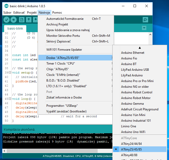
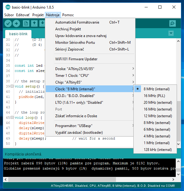
There are several options in the Clock menu item. Because the ATtiny85 microcontroller has only 8 pins, you will usually only use those that are labeled internal. The only exception is the 16 MHz PLL, which allows you to set the same frequency as in the Arduino. Internally, the special mode of the microcontroller, which can generate very high frequencies, can also used as clock source for the microcontroller.
Higher frequencies are used when a base frequency of 1 MHz is not enough. The microcontroller then performs several instructions. You pay for it in the form of higher energy consumption. In this case, suppose we need a frequency of 8 MHz and set it in the menu.
Another choice is the choice of the programmer. If you have Arduino, you can program ATtiny85 using it and select Arduino as ISP. If you have USBasp purchased, then you select this item. Both methods are comparable and it's up to you to choose.

The last step follows. In the menu, you select Burn bootloader. You can program the fuses in the microcontroller and switch the frequency.

Let's now examine what's happening when you burn the bootloader. This feature was originally designed to load the bootloader into the Arduino. It provides convenient programming via the serial port. At the same time it also sets the fuses. The fuses are dedicated memory in a microcontroller to set the behavior of the microcontroller after start-up. In the datasheet, this area is described in Chapter 20.2 Fuse Bytes. The tiny board microcontrollers are set without bootloader in the ATTinyCore, so this menu item only sets the fuses.
1 MHz or 8 MHz
If you compared the fuse setting for 1 MHz and 8 Mhz, the difference would be a single bit. It is called CKDIV8 and is located in Fuse Low Byte. You can also look at Arduino in particular for fuse settings. The ATTinyCore core is located in the C:\Users\[your name]\AppData\Local\Arduino15\packages\ATTinyCore\hardware\avr\1.1.4\boards.txt file. The path to the file may vary slightly. Everything depends on your version of Windows. The file contains many rows, but you can easily recognize the fuses in it. I shortened the contents of the file so that the fuse setting can be easily identified.
attinyx5.name=ATtiny25/45/85
attinyx5.bootloader.extended_fuses=0xFF
attinyx5.menu.chip.85=ATtiny85
attinyx5.menu.chip.85.build.mcu=attiny85
attinyx5.menu.chip.85.upload.maximum_size=8192
attinyx5.menu.chip.85.upload.maximum_data_size=512
attinyx5.menu.clock.8internal=8 MHz (internal)
attinyx5.menu.clock.8internal.bootloader.low_fuses=0xE2
attinyx5.menu.clock.8internal.build.f_cpu=8000000L
attinyx5.menu.clock.8internal.bootloader.file=empty/empty_all.hex
attinyx5.menu.clock.1internal=1 MHz (internal)
attinyx5.menu.clock.1internal.bootloader.low_fuses=0x62
attinyx5.menu.clock.1internal.build.f_cpu=1000000L
attinyx5.menu.clock.1internal.bootloader.file=empty/empty_all.hex
When setting up fuses, you have to understand what you are doing. By inappropriate settings, you can get the microcontroller into a state where you can not communicate with it. For example, if you select a frequency with an external clock, you will need to connect a crystal, otherwise you will not go any more with the microcontroller. In normal use, you'll need the settings I mentioned in the text. There is no danger that you will not want the microcontroller to go into a state in which it stops communicating.
Experiments
What happens when you have a microcontroller set by fuses at one frequency and you select a different frequency in the menu? At first glance, you have nothing to do. Use the program Blink from the previous chapter to try out what happens. Depending on the combination selected, the LED will blink or very slow or very fast. This is because the delay function is controlled internally by the menu setting, which assumes you have the same frequency in the microcontroller. And according to that, the internal time is counted. And when the values do not match, the time in the microcontroller accelerates or slows down, because the function counts the time according to the set frequency from which it can deduce how many instructions must wait until the time elapses.
03.01.2018