ATtiny85 - PWM
Zápisník experimentátora
Hierarchy: ATtiny85
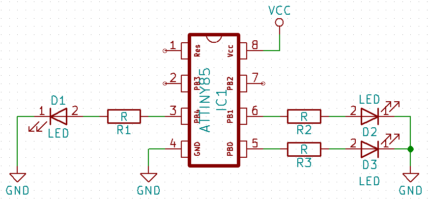
ATtiny85 has 3 PWM outputs. They are located on pins 0, 1 and 4. In this article we show how PWM is used. PWM (pulse width modulation) is an acronym for pulse width modulation of the signal by means of a change of the pulse width. It is an efficient way to control the electrical power delivered to the load. Arduino users meet this term when they control the brightness of the LED or the fan speed.
In the examples I will use an LED (max 20 mA) which is connected via a resistor directly to the pin of the microcontroller. If you want to connect a more powerful LED (1 W - 300 mA, 3W - 700 mA), you will need to use additional components. A good example of how to do this can be found in my Lighting RC model aircraft project. We will not regulate the fan speed, but also in this case you need to know what maximum current you are going to supply and if you exceed the possibilities of the microcontroller (about 20-40 mA), you need to use additional components.
PWM
I have written several examples that show the basic work with PWM. In the first example, the PWM signal is changed from 0-255 on all available PWM outputs. I use the NUM_DIGITAL_PINS macro to use all digital pins. Not every pin has a PWM output and therefore I use the function digitalPinHasPWM to check. If the pin supports PWM, I set the PWM value to it using the function analogWrite.
In this example you will notice that the brightness of the LED diodes is uneven. You feel like it's gonna light up so fast and then the brightness of the diode does not change. This is due to the fact that the human eye does not see linear increase of brightness with PWM as linear.
int pwm_value = 0;
int dms = 20;

void setup() {
  for (int i = 0; i < NUM_DIGITAL_PINS; i++)
    pinMode(i, OUTPUT);
}

void loop() {
  for (int i = 0; i < NUM_DIGITAL_PINS; i++) {
    if (digitalPinHasPWM(i))
      analogWrite(i, pwm_value);
  }

  pwm_value = (pwm_value + 1) % 255;
  delay(dms);
}
PWM with gamma correction
In the second example, I use the gamma correction table to adjust the brightness of the LED to the human eye. Now, your eye is better able to see PWM change as a linear change of brightness. But it's not perfect. If you look at the gamma correction table, you will notice that the values at the beginning of the table are so small that, due to rounding, many items in the table have the same value. This is because we only have 8-bit value and so we are unable to use gamma corrections with sufficient precision. In the example, this means that at low levels of brightness, your eye has the feeling that the brightness changes with a small steps.
int pwm_value = 0;
int dms = 20;

// table of exponential values
// generated for values of i from 0 to 255 -> x=round( pow( 2.0, i/32.0) - 1);
const byte table[] PROGMEM = {
  0,   0,   0,   0,   0,   0,   0,   0,   0,   0,   0,   0,   0,   0,   0,   0,
  0,   0,   0,   1,   1,   1,   1,   1,   1,   1,   1,   1,   1,   1,   1,   1,
  1,   1,   1,   1,   1,   1,   1,   1,   1,   1,   1,   2,   2,   2,   2,   2,
  2,   2,   2,   2,   2,   2,   2,   2,   2,   2,   3,   3,   3,   3,   3,   3,
  3,   3,   3,   3,   3,   3,   4,   4,   4,   4,   4,   4,   4,   4,   4,   5,
  5,   5,   5,   5,   5,   5,   5,   6,   6,   6,   6,   6,   6,   6,   7,   7,
  7,   7,   7,   8,   8,   8,   8,   8,   9,   9,   9,   9,   9,  10,  10,  10,
 10,  11,  11,  11,  11,  12,  12,  12,  12,  13,  13,  13,  14,  14,  14,  15,
 15,  15,  16,  16,  16,  17,  17,  18,  18,  18,  19,  19,  20,  20,  21,  21,
 22,  22,  23,  23,  24,  24,  25,  25,  26,  26,  27,  28,  28,  29,  30,  30,
 31,  32,  32,  33,  34,  35,  35,  36,  37,  38,  39,  40,  40,  41,  42,  43,
 44,  45,  46,  47,  48,  49,  51,  52,  53,  54,  55,  56,  58,  59,  60,  62,
 63,  64,  66,  67,  69,  70,  72,  73,  75,  77,  78,  80,  82,  84,  86,  88,
 90,  91,  94,  96,  98, 100, 102, 104, 107, 109, 111, 114, 116, 119, 122, 124,
127, 130, 133, 136, 139, 142, 145, 148, 151, 155, 158, 161, 165, 169, 172, 176,
180, 184, 188, 192, 196, 201, 205, 210, 214, 219, 224, 229, 234, 239, 244, 250
};

void setup() {
  for (int i = 0; i < NUM_DIGITAL_PINS; i++)
    pinMode(i, OUTPUT);
}

void loop() {
  for (int i = 0; i < NUM_DIGITAL_PINS; i++) {
    if (digitalPinHasPWM(i))
      analogWrite(i, pgm_read_byte(&table[pwm_value]));
  }

  pwm_value = (pwm_value + 1) % 255;
  delay(dms);
}
PWM with shifting
The last example is just a game with three PWM outputs. On individual LEDs, the brightness is phase-shifted and individual LEDs give the impression that they will turn gradually on and go out.
int pwm_value = 0;
const int dms = 20;
const int pwm_shift = 255/3;

// table of exponential values
// generated for values of i from 0 to 255 -> x=round( pow( 2.0, i/32.0) - 1);
const byte table[] PROGMEM = {
  0,   0,   0,   0,   0,   0,   0,   0,   0,   0,   0,   0,   0,   0,   0,   0,
  0,   0,   0,   1,   1,   1,   1,   1,   1,   1,   1,   1,   1,   1,   1,   1,
  1,   1,   1,   1,   1,   1,   1,   1,   1,   1,   1,   2,   2,   2,   2,   2,
  2,   2,   2,   2,   2,   2,   2,   2,   2,   2,   3,   3,   3,   3,   3,   3,
  3,   3,   3,   3,   3,   3,   4,   4,   4,   4,   4,   4,   4,   4,   4,   5,
  5,   5,   5,   5,   5,   5,   5,   6,   6,   6,   6,   6,   6,   6,   7,   7,
  7,   7,   7,   8,   8,   8,   8,   8,   9,   9,   9,   9,   9,  10,  10,  10,
 10,  11,  11,  11,  11,  12,  12,  12,  12,  13,  13,  13,  14,  14,  14,  15,
 15,  15,  16,  16,  16,  17,  17,  18,  18,  18,  19,  19,  20,  20,  21,  21,
 22,  22,  23,  23,  24,  24,  25,  25,  26,  26,  27,  28,  28,  29,  30,  30,
 31,  32,  32,  33,  34,  35,  35,  36,  37,  38,  39,  40,  40,  41,  42,  43,
 44,  45,  46,  47,  48,  49,  51,  52,  53,  54,  55,  56,  58,  59,  60,  62,
 63,  64,  66,  67,  69,  70,  72,  73,  75,  77,  78,  80,  82,  84,  86,  88,
 90,  91,  94,  96,  98, 100, 102, 104, 107, 109, 111, 114, 116, 119, 122, 124,
127, 130, 133, 136, 139, 142, 145, 148, 151, 155, 158, 161, 165, 169, 172, 176,
180, 184, 188, 192, 196, 201, 205, 210, 214, 219, 224, 229, 234, 239, 244, 250
};

void setup() {
  for (int i = 0; i < NUM_DIGITAL_PINS; i++)
    pinMode(i, OUTPUT);
}

void loop() {
  int ii = 0;
  for (int i = 0; i < NUM_DIGITAL_PINS; i++) {
    if (digitalPinHasPWM(i)) {
      int value = pwm_value + pwm_shift*ii;
      value = (value + 1) % 255;
      analogWrite(i, pgm_read_byte(&table[value]));
      ii++;
    }
  }

  pwm_value = (pwm_value + 1) % 255;
  delay(dms);
}
Source code
The source code is located on the GitHub server.
07.08.2018