Timer1 - 8, 9 and 10-bit PWM
Zápisník experimentátora
Hierarchy: Časovač (timer)
The function analogWrite in Arduino only supports 8-bit mode. You can also turn on 9 and 10-bit mode on the timer1, which will give you a higher resolution for the PWM signal. In this article, we will show you how to do this.
Used parts
- Arduino Pro Mini {linkArduino}
- Breadboard {linkBreadBoard}
- LED {linkLed}
- Resistor 1k {linkR}
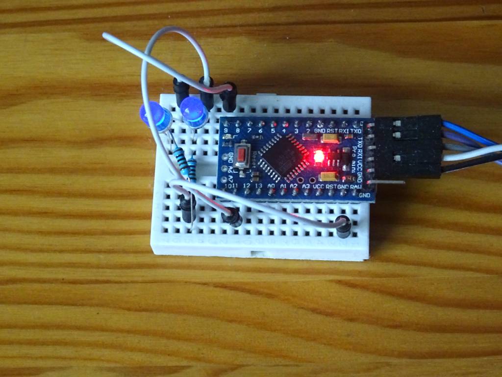
The electrical circuit is simple in this case. All you need is an Arduino and 2 LEDs and 2 resistors. Connect them to pins 9 and 11 so that they are on timers 1 and 2. I usually use blue LEDs and 1k resistors. That's enough for the LED to glow but not blind your eyes at the same time.
I have written four examples to illustrate the settings of the system registers that control PWM. All examples contain debug statements from the registers to the serial port, which look exactly as in the datasheet of the ATmega328P microcontroller. I have given a detailed description of registry debugging in a separate article. Therefore, I will not describe the dump.h file in this article, which contains the source code to visualize the contents of the system registry.
- Listing of system registers on timers 1 and 2 as set by Arduino at program start. Timer1 is set to mode 1 (PWM, phase correct, 8-bit, prescaler 64). Timer2 is set to mode 1 (PWM, phase correct, prescaler 64).
- Timer2 fast PWM 8-bit. Setting mode 3 and the smallest PWM value.
- Timer1 fast PWM 8-bit. Setting mode 5 and the smallest PWM value.
- Timer1 fast PWM 8, 9 and 10-bit and comparison with timer2. The smallest value is set on both timers, which allows you to compare the brightness of the LED. At higher resolutions, it is clear that the LED is less lit. Mode 5, 6 and 7 settings.
Example 1 - Listing system registers
The first example is to find out how Arduino sets up the registers after startup. That is, before the setup and loop functions. When you dive into the source code of the function (1, 2), you will find there a lot of conditional code, the meaning of which is not always completely clear. This is because the function takes into account a larger number of microcontrollers, which set the same function using different bits in different registers. I set the smallest PWM values on pins 9 and 11 so that the brightness of both LEDs could be compared. The difference is essentially imperceptible to the naked eye.
#include "dump.h"

DREG(TCCR2A, COM2A1, COM2A0, COM2B1, COM2B0, RESERVED, RESERVED, WGM21, WGM20)
DREG(TCCR2B, FOC2A, FOC2B, RESERVED, RESERVED, WGM22, CS22, CS21, CS20)
DREG(TCCR1A, COM1A1, COM1A0, COM1B1, COM1B0, RESERVED, RESERVED, WGM11, WGM10)
DREG(TCCR1B, FOC1A, FOC1B, RESERVED, RESERVED, WGM12, CS12, CS11, CS10)

void setup() {
  pinMode(11, OUTPUT); // TIMER2A
  pinMode(9, OUTPUT);  // TIMER1A
  analogWrite(11, 1);  // minimal PWM value
  analogWrite(9, 1);   // minimal PWM value

  Serial.begin(9600);
  Serial.println("PWM modes");

  // TIMER2
  Serial << _(TCCR2A);
  Serial << _(TCCR2B);
  DUMPVAL(OCR2A)
  DUMPVAL(OCR2B)

  // TIMER1
  Serial << _(TCCR1A);
  Serial << _(TCCR1B);
  DUMPVAL(OCR1A)
  DUMPVAL(OCR1B)
}

void loop() {
}
Listing from the program. By comparing the report with the description in the datasheet and with the description in the Arduino source code, we see that both timers set the PWM phase correct mode with the prescaler 64. They set this mode for better motor control. It does not make sense for use with LEDs, so in the following examples we will switch the mode to fast PWM.
PWM modes
TCCR2A=10000001: COM2A1 WGM20
TCCR2B=100: CS22
OCR2A=1
OCR2B=0
TCCR1A=10000001: COM1A1 WGM10
TCCR1B=11: CS11 CS10
OCR1A=1
OCR1B=0
Example 2 - Timer2 fast PWM
Switch mode from phase correct PWM to fast PWM. The change is only minor. Only one bit in the register changes. Timer2 only supports 8-bit modes, so visually we have not changed from the previous state. But at least we've shown that we can control system registers by setting bits.
#include "dump.h"

DREG(TCCR2A, COM2A1, COM2A0, COM2B1, COM2B0, RESERVED, RESERVED, WGM21, WGM20)
DREG(TCCR2B, FOC2A, FOC2B, RESERVED, RESERVED, WGM22, CS22, CS21, CS20)

void setup() {
  pinMode(11, OUTPUT); // TIMER2A
  analogWrite(11, 1);  // minimal PWM value

  Serial.begin(9600);
  Serial.println("PWM modes");

  // TIMER2
  Serial << _(TCCR2A);
  Serial << _(TCCR2B);
  DUMPVAL(OCR2A)
  DUMPVAL(OCR2B)

  Serial.println("TIMER2 Mode 3: Fast PWM");
  TCCR2A = _BV(COM2A1) | _BV(WGM21) | _BV(WGM20);
  Serial << _(TCCR2A);
  Serial << _(TCCR2B);
  DUMPVAL(OCR2A)
  DUMPVAL(OCR2B)
}

void loop() {
}
Listing from the program. You can compare the statement with the datasheet and it shows us that we correctly switched the WGM21 bit.
PWM modes
TCCR2A=10000001: COM2A1 WGM20
TCCR2B=100: CS22
OCR2A=1
OCR2B=0
TIMER2 Mode 3: Fast PWM
TCCR2A=10000011: COM2A1 WGM21 WGM20
TCCR2B=100: CS22
OCR2A=1
OCR2B=0
Example 3 - Timer1 fast PWM
Switch mode on timer1. Again, we just change the phase correct PWM to fast PWM. In this case, I left both LEDs set so that we could visually compare if they were about the same. In this example, it can be seen that the mode setting bits are in two registers. We need to set them up correctly to get the right result.
And now, after checking this program one after the other, I see that there is a small error in it. I forgot to add the WGM13 bit to the TCCR1B register listing. In this case, it does not matter, because this bit is used only in higher modes and I did not use them in the example.
#include "dump.h"

DREG(TCCR1A, COM1A1, COM1A0, COM1B1, COM1B0, RESERVED, RESERVED, WGM11, WGM10)
DREG(TCCR1B, FOC1A, FOC1B, RESERVED, RESERVED, WGM12, CS12, CS11, CS10)

void setup() {
  pinMode(9, OUTPUT);  // TIMER1A
  analogWrite(9, 1);   // minimal PWM value
  pinMode(11, OUTPUT); // TIMER2A
  analogWrite(11, 1);  // minimal PWM value

  Serial.begin(9600);
  Serial.println("PWM modes");

  // TIMER1
  Serial << _(TCCR1A);
  Serial << _(TCCR1B);
  DUMPVAL(OCR1A)
  DUMPVAL(OCR1B)

  Serial.println("TIMER1 Mode 5: Fast PWM 8-bit");
  TCCR1A = (1 << WGM10) | (1 << COM1A1);
  TCCR1B = (1 << WGM12) | (1 << CS11) | (1 << CS10);
  Serial << _(TCCR1A);
  Serial << _(TCCR1B);
  DUMPVAL(OCR1A)
  DUMPVAL(OCR1B)
}

void loop() {
}
Listing from the program. And again, check according to the datasheet to see if we set everything up correctly.
PWM modes
TCCR1A=10000001: COM1A1 WGM10
TCCR1B=11: CS11 CS10
OCR1A=1
OCR1B=0
TIMER1 Mode 5: Fast PWM 8-bit
TCCR1A=10000001: COM1A1 WGM10
TCCR1B=1011: WGM12 CS11 CS10
OCR1A=1
OCR1B=0
Example 4 - 8, 9 and 10-bitové PWM
The last example shows us how the minimum value in the OCR1A register is reflected in the case of a PWM mode change. The higher the bit resolution, the less the LED is lit. In the example, the mode changes every two seconds and you can compare the resulting brightness of the LED with the still unchanged value on the second LED.
#include "dump.h"

DREG(TCCR1A, COM1A1, COM1A0, COM1B1, COM1B0, RESERVED, RESERVED, WGM11, WGM10)
DREG(TCCR1B, FOC1A, FOC1B, RESERVED, RESERVED, WGM12, CS12, CS11, CS10)

void setup() {
  pinMode(9, OUTPUT);  // TIMER1A
  analogWrite(9, 1);   // minimal PWM value
  pinMode(11, OUTPUT); // TIMER2A
  analogWrite(11, 1);  // minimal PWM value

  Serial.begin(9600);
  Serial.println("PWM modes");
}

void loop() {
  Serial.println("TIMER1 Mode 5: Fast PWM 8-bit");
  TCCR1A = (1 << WGM10) | (1 << COM1A1);
  TCCR1B = (1 << WGM12) | (1 << CS11) | (1 << CS10);
  Serial << _(TCCR1A);
  Serial << _(TCCR1B);
  delay(2000);
  Serial.println("TIMER1 Mode 6: Fast PWM 9-bit");
  TCCR1A = (1 << WGM11) | (1 << COM1A1);
  TCCR1B = (1 << WGM12) | (1 << CS11) | (1 << CS10);
  Serial << _(TCCR1A);
  Serial << _(TCCR1B);
  delay(2000);
  Serial.println("TIMER1 Mode 7: Fast PWM 10-bit");
  TCCR1A = (1 << WGM11) | (1 << WGM10) | (1 << COM1A1);
  TCCR1B = (1 << WGM12) | (1 << CS11) | (1 << CS10);
  Serial << _(TCCR1A);
  Serial << _(TCCR1B);
  delay(2000);
}
Listing from the program. Every two seconds, the mode changes and the contents of the registers are written to the serial port.
PWM modes
TIMER1 Mode 5: Fast PWM 8-bit
TCCR1A=10000001: COM1A1 WGM10
TCCR1B=1011: WGM12 CS11 CS10
TIMER1 Mode 6: Fast PWM 9-bit
TCCR1A=10000010: COM1A1 WGM11
TCCR1B=1011: WGM12 CS11 CS10
TIMER1 Mode 7: Fast PWM 10-bit
TCCR1A=10000011: COM1A1 WGM11 WGM10
TCCR1B=1011: WGM12 CS11 CS10
Source code
The source code is located on the GitHub server.
Video
17.06.2020