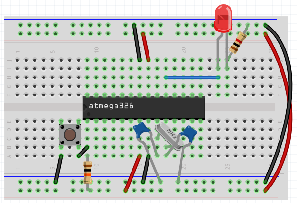
ATmega328P on a breadboard
Page
This page is a guide on how to put together the core of the Arduino on the breadboard. ATmega328P-PU is a microcontroller around which Arduino Uno is built. This manual builds a version that runs at 16 MHz. Programming this microcontroller can be as instructed by Arduino as an ISP programmer.
Breadboard
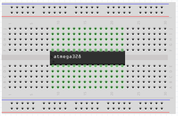
We will need a breadboard that has 30 columns. It fits neatly microcontroller, reset circuit, crystal and LED.
Microcontroller
Insert the ATmega328P into the breadboard so that PIN1 is at position e9. This will give us plenty of space on both sides where we will place the reset button and the LED.
Power supply
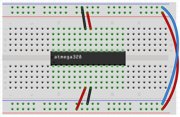
Connect both longitudinal paths that are designed for + 5V and GND. Add a link between a16 and GND and j15 and GND. Add a connection between a15 and +5 V and j16 and +5 V. The j15 and j16 connections may not necessarily be connected, because they provide analogue measurement. Sometimes a 0.1 μF capacitor between each supply pin and GND is added in such schemes. It is a filter capacitor whose task is to compensate for voltage fluctuations. It is positioned as close as possible to the microcontroller. If you connect such a circuit on the circuit board, you should add the capacitors there.
Reset
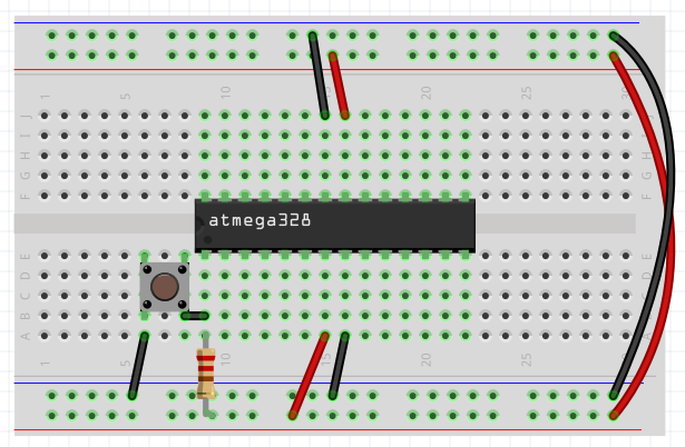
You can reset the circuit at any time by pushing the button. Put the button next to the microcontroller. Different types are produced that vary slightly in size. My position was at c6-e8. Make sure they are horizontally in the conductor path with the microcontroller. Place a 10k resistor between a9 and +5 V.
At position e9 is pin 1 of microcontroller. Thanks to the pull-up resistor, it is held at +5 V. By pressing the button, the pin will be connected to the GND and will reset the microcontroller. For this to work, it is still necessary to connect a6 and GND and a8 and b9.
Crystal
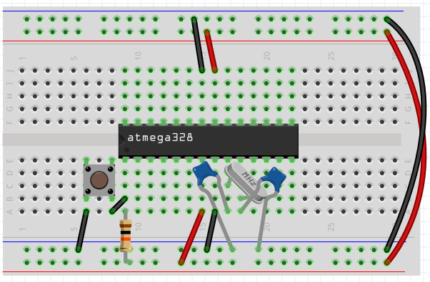
Crystal is needed only if we want to have an identical Arduino at 16 MHz. Connect the 22 pF capacitor between a17 and GND. Connect a 22 pF capacitor between a18 and GND. Connect the 16 MHz crystal between b17 and b18. By default, the microcontroller is factory set to 1 MHz. In order to operate at a higher frequency, a crystal is needed and the fuses must be set.
LED
The LED serves us to indicate the correct operation of the circuit. We connect it to the same pin where the Arduino Uno LED is on the digital output 13. Connect the h18 and h24. Place the LED on i24 (anode - longer leg) and i25. Connect resistor 1k between j25 and GND. In other tutorials you can also meet with the value of 330R. The resistor value sets the current flowing through the LED. Today, super bright LEDs are sold, so the value of 1k will be enough for you.
Connecting Arduino Uno as an ISP
- 10 uF electrolytic capacitor between RESET and GND on Arduino. Plus is connected to RESET. This prevents Arduino from being reset. First try it without a capacitor. My experience is, that it is not needed for newer versions of IDE.
- 5 V from Arduino to a 5 V on breadboard.
- GND from Arduino to GND on breadboard.
- PIN10 from Arduino to
d9. - PIN11 from Arduino to
j20. - PIN12 from Arduino to
j19. - PIN13 from Arduino to
j18.
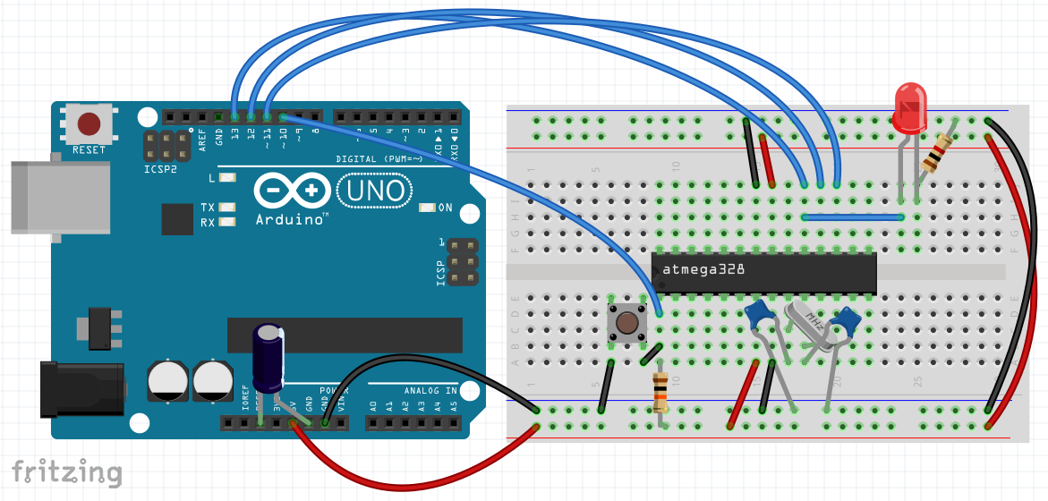
Now the circuit is ready for programming and testing. See the hyperlink at the beginning of this page for an accurate description. Be sure to set all parameters correctly. Frequently, the mistake is that you do not correctly set the programmer's version to ArduinoISP. Take care also to set fuses.
Placed on the breadboard
In order to get an idea of what it really looks like, I've also added photographs.
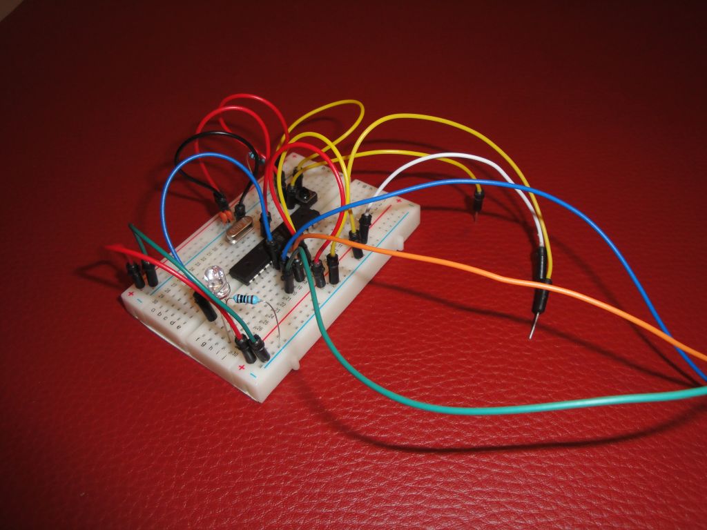
On the first picture, it is made with interconnecting cables. A little confusing.
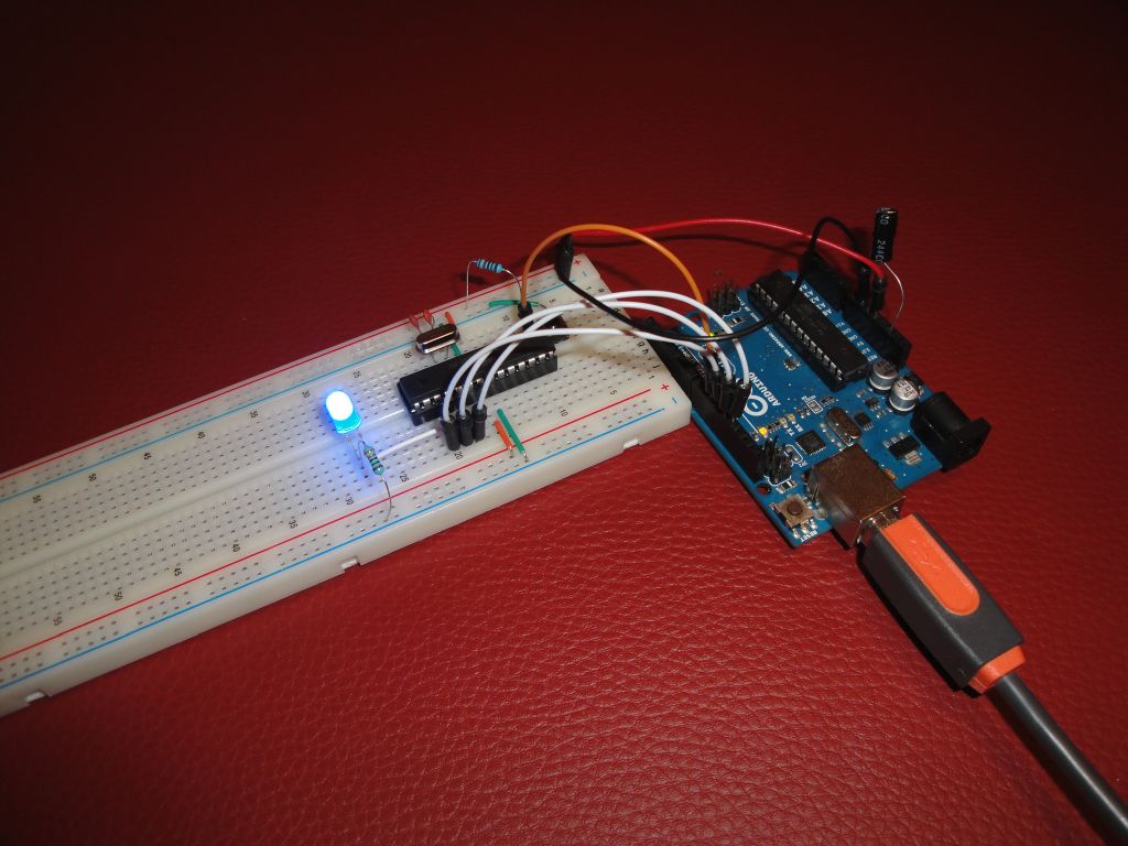
In the second picture, it is made using interconnecting wires that can be bought in a cheap package. The result can be really clear.
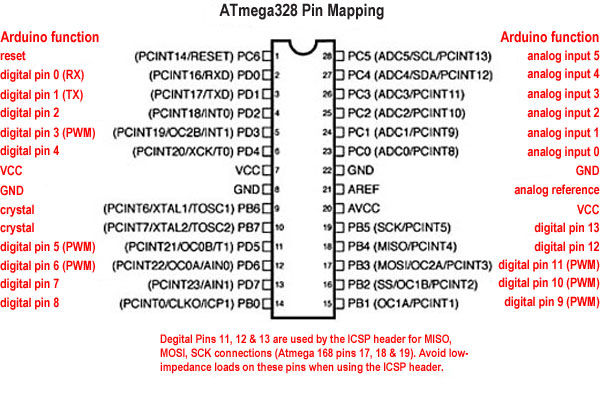
Pin mapping
Why is it done this way?
Because the current consumption of the microcontroller involved is minimal. Arduino has many parts that consumes a current. With such a connection, the consumption is only 16 mA. Arduino UNO has a consumption of approximately 50 mA.
If you want to get the power even lower, the microcontroller can fall asleep. If one does not want to be very exhausted by exploring sleep modes, he will use the prebuild solution through the Narcoleptic library.
02.07.2017