Arduino sequencer - the SOS signal
Zápisník experimentátora
For today's topic I chose an interesting area. We will use the Arduino to generate the SOS signal. The signal will be displayed using the LED. We will study several ways of generating a signal. Finally, we end up using sequencer and timer. This will be our top in the art of programming. The created sequencer will serve as a basis for the forthcoming article about semaphore control and signaling protocol for ESP8266.
Purchase of components
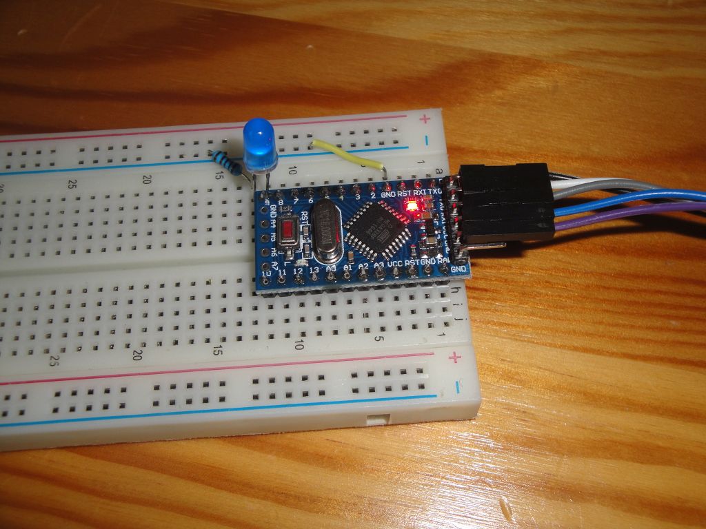
Arduino Pro Mini is on the photo. It does not limit you, you can use basically any Arduino.
- Arduino Pro Mini (link) - I used this Arduino.
- Breadboard (link) - It is used to insert all components.
- Blue LED - Blue color is suitable because the LED has high brightness and you can also see fine changes in brightness.
- Resistor 1k - The resistor limits the current flowing through the LED. Because we use a high-luminous LED, just a couple of milliamps is enough for us.
Connection is simple. The LED will be connected to pin 9. We will connect it using a resistor to GND output from Arduino.
SOS
The SOS signal in the Morse alphabet looks like this . . . - - - . . .. We will show its creation using these algorithms. Algorithms are ordered from the most primitive to the smartest. Because we are going to create a sequencer, our goal will be the last algorithm.
- Brutal force
- Functions
- Sequencer
- Sequencer and timer
Generate with brutal force
When I prepared the background for the article, I encountered a number of different implementations. Therefore, it is also worth mentioning the generation of the signal with brutal force. Each point, line, and space in SOS is build using digitalWrite and delay. It is the worst possible way of programming, but it will work. So we can not totally reject it just because you are typing same code again and again. I'm not going to give an example here, because then that page would be three kilometers long. But when you write the words Arduino SOS into Google, you will find a good number of examples.
Generate using the functions
If you look at how the signal looks, it immediately comes to mind that it can be created using three short sections that represent each letter. And because in the SOS signal each letter is like a triple of the same characters, it can be quite skillfully done with functions. On the Internet, I found a nice example that I just slightly modified. You can find the original source as a link in the source text on GitHub.
The example does not generate SOS exactly according to the Morse alphabet. But as a demonstration it's good. The individual characters are clearly distinguishable and last long enough for SOS to be recognized by the untrained eye. The example is in sequencer_sos_01.ino.
int LED = 9;
int s = 300;
int o = 800;

void setup() {
  // put your setup code here, to run once:
  pinMode(LED, OUTPUT);
}

void character(int speed) {
  digitalWrite(LED, HIGH);
  delay(speed);
  digitalWrite(LED, LOW);
  delay(300);
}

void loop() {
  // put your main code here, to run repeatedly:
  for (int x = 1; x <= 3; x++) {
    character(s);
  }
  delay(100);
  for (int x = 1; x <= 3; x++) {
    character(o);
  }
  delay(100);
  for (int x = 1; x <= 3; x++) {
    character(s);
  }
  delay(2000);
}
Sequencer
Sequencers are very simple tools. They send the required value at regular intervals. In our case, we create a sequencer that will simulate the previous example. In 100 ms intervals, turn on or off the LED. You will see that the result is the same as the program that created SOS characters with functions. The sequencer has the advantage that if the program requirements change, the program itself does not need to change and only the sequence changes.
The program may seem longer, but that's just because I've added extras to the serial port to see what the sequencer does. Sequence is stored in the variable sequence. It is the recorded LED flashing at intervals of 100 ms. I chose this interval because the original program with functions used such a division. Because of the RAM, I have stored the variable in Flash memory, which is caused by the PROGMEM modifier.
The sequencer is created in the Sequencer class. It has only two functions. In the constructor, we denote the sequence data and in the next function we move forward in sequence each time and set the LED to HIGH or LOW. Run the serial port monitor and see the whole sequencer activity. The example is in the sequencer_sos_02.ino file.
const int LED = 9;
// 1 char = 100 ms
const char PROGMEM sequence[] =
  "111000111000111000"
  "0"
  "111111110001111111100011111111000"
  "0"
  "111000111000111000"
  "00000000000000000000";
const int sequence_length = sizeof(sequence)/sizeof(char);

class Sequencer {
  char *data;
  int len;
  int pos;

public:
  Sequencer(char *_data, int _len)
  : data(_data), len(_len), pos(0)
  {}

  void next() {
    char b = pgm_read_byte(&data[pos]);
    Serial.print(b);
    digitalWrite(LED,b=='1');
    pos++;
    if(pos%10==0)
      Serial.println("");
    if(pos==len) {
      pos=0;
      Serial.println("");
      Serial.println("-- restart --");
    }
  }
};

Sequencer seq(sequence,sequence_length);

void setup() {
  pinMode(LED, OUTPUT);
  Serial.begin(115200);
  Serial.print("sequence_length: ");
  Serial.println(sequence_length);
}

void loop() {
  seq.next();
  delay(100);
}
Sequencer and timer
The previous example was timed for clarity by using the function delay. Now we can make our program as efficient as possible and use timer1 for timing. Using the calculator, set the timer to 10 Hz (every 100 ms), and the next function of the Sequencer class will be called from the TIMER1_COMPA_vect interrupt. From the example, I removed all the serial port outputs. In this form, the program is short and understandable. The example is in sequencer_sos_03.ino.
#define ledPin 9

// 1 char = 100 ms
const char PROGMEM sequence[] =
  "111000111000111000"
  "0"
  "111111110001111111100011111111000"
  "0"
  "111000111000111000"
  "00000000000000000000";
const int sequence_length = sizeof(sequence)/sizeof(char);

class Sequencer {
  char *data;
  int len;
  int pos;

public:
  Sequencer(char *_data, int _len)
  : data(_data), len(_len), pos(0)
  {}

  void next() {
    char b = pgm_read_byte(&data[pos]);
    digitalWrite(ledPin,b=='1');
    pos++;
    if(pos==len)
      pos=0;
  }
};

Sequencer seq(sequence,sequence_length);

void setupTimer1() {
  noInterrupts();
  // Clear registers
  TCCR1A = 0;
  TCCR1B = 0;
  TCNT1 = 0;

  // 10 Hz (16000000/((6249+1)*256))
  OCR1A = 6249;
  // CTC
  TCCR1B |= (1 << WGM12);
  // Prescaler 256
  TCCR1B |= (1 << CS12);
  // Output Compare Match A Interrupt Enable
  TIMSK1 |= (1 << OCIE1A);
  interrupts();
}

void setup() {
  pinMode(ledPin, OUTPUT);
  setupTimer1();
}

void loop() {
}

ISR(TIMER1_COMPA_vect) {
  seq.next();
}
Čo ďalej?
I chose an extremely simple example of the SOS signal. We have shown the principle of creating a sequencer. In the continuation of the article we will deal with the issue of crossing. We will use two semaphores with three lights and you will see that using a sequencer, the code is trivially simple. Who wants to know how to drive 6 pins at once and how to store them in a sequencer, the guideline will find in the article 8x PWM on one Arduino.
Source code
The source code is located on the GitHub server.
07.09.2017