DS1307 and square wave output
Zápisník experimentátora
Hierarchy: DS1307 Hodiny reálneho času
The integrated circuit DS1307 has one pin labeled as SQW. It is possible to enable signal generation with square wave on it. The generated signal may be set at a different frequency. In this article we will show the frequency setting of the signal and how to connect it to the interrupt in the Arduino.
Used parts
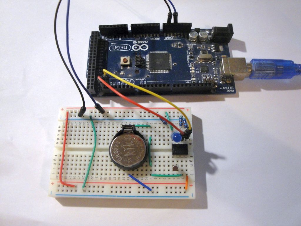
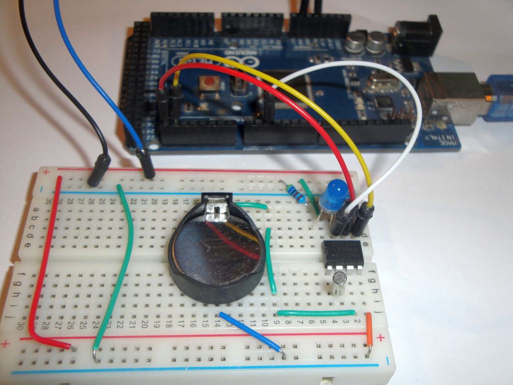
I used the following components:
- Arduino Mega 2560 ((link)
- DS1307 (link)
- Breadboard (link)
- 3x 10k resistor - SCL, SDA, SQW
- 1x blue LED diode
- Battery CR2032 (link)
- Battery Socket Holder (link)

Signal with square wave output
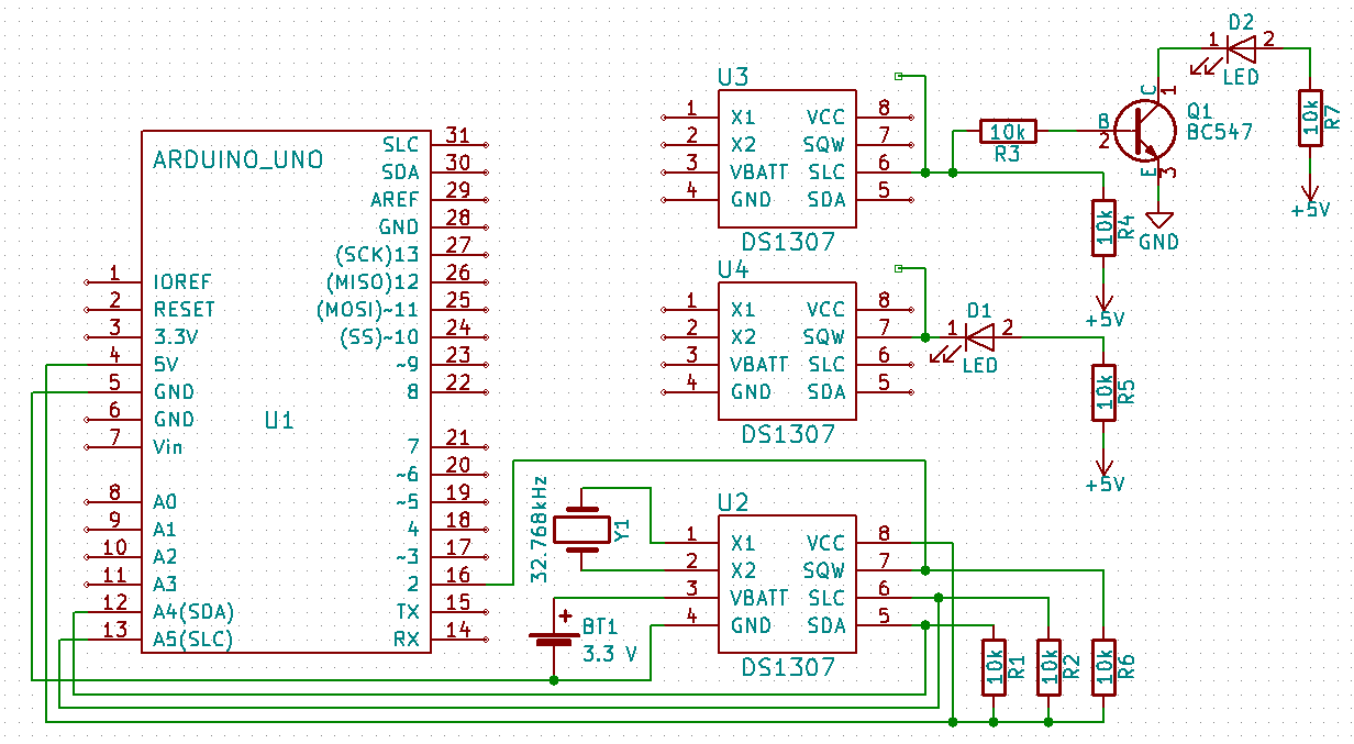
SQW signal output is connected as transistor with open collector. In order to detect a signal, it is necessary to connect the terminal using a resistor to the VCC. The value of the resistor is not critical. The resistor limits the magnitude of the current and in this case serves only as a signal. Suitable values are 10k or 4k7. In any case, do not connect it without a resistor because you would shorten VCC and GND.

The sketches
I wrote two examples:
- set_sqw_1 - Example to turn on the signal with a square wave output. The program is set to 1 Hz and the other frequency settings are remarked in the code (4,096 kHz, 8,192 kHz and 32,768 kHz). You can connect the LED to the SQW output and watch the flashes at 1 Hz.
- set_sqw_interrupt - In this example, a signal with a square wave of 1 Hz is turned on. The output is connected to the pin, which provides interrupt 0 in Arduino. Interrupt is set on the falling edge. The result is blinking with an internal LED flashing with the half frequency. This is because it only responds to the falling edge when it switches the status of the internal LED.
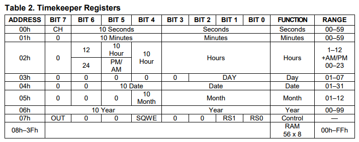
Both programs use similar settings in the integrated circuit register. By setting the SQWE bit, signal generation with square wave is switched on, and the bit setting RS1 and RS2 sets the frequency. Four different frequencies can be set. Because we want to see the generated signal in our programs, we will use a frequency of 1 Hz.
set_sqw_1
The first program builds on the previous article where we created the DS1307RTCex class, which writes to the serial port the RAM content in the integrated circuit. I have left the RAM content listing and added only the function setSQW. This function sets the contents of the register 7 to set the waveform of the generated signal.
The wiring diagram according to the schematic for the U2 circuit must be used. In such a connection we would generate a signal that would come to the D2 pin in the Arduino, but we would not see anything. That's why I used an alternative U4 circuit. The D1 diode visualizes the waveform. I used a blue LED, but it should work any diode.
#include <Wire.h>
#include <TimeLib.h>
#include <DS1307RTC.h>

#define DS1307_CTRL_ID 0x68

class DS1307RTCex : public DS1307RTC {
    uint8_t ram[64];

  public:
    DS1307RTCex() : DS1307RTC() {}

    bool readRam() {
      uint8_t *ptr = ram;

      for (uint8_t x = 0; x <= 4; x++) {
        Wire.beginTransmission(DS1307_CTRL_ID);
        Wire.write((uint8_t)x * 16);
        if (Wire.endTransmission() != 0)
          return false;

        uint8_t sz = 16;
        // block
        Wire.requestFrom(DS1307_CTRL_ID, 16);
        if (Wire.available() < 16) return false;
        while (sz) {
          *ptr++ = Wire.read();
          sz--;
        }
      }

      return true;
    }

    void dump() {
      uint8_t nRows = 4;
      char    asciiDump[17];
      int     value;

      for (uint8_t r = 0; r < nRows; r++) {
        uint8_t a = 16 * r;

        Serial.print(F("0x"));
        if ( a < 16 * 16 * 16 ) Serial.print(F("0"));
        if ( a < 16 * 16 ) Serial.print(F("0"));
        if ( a < 16 ) Serial.print(F("0"));
        Serial.print(a, HEX); Serial.print(F(" "));

        for (int c = 0; c < 16; c++) {
          value = ram[a + c];
          if (value < 16)
            Serial.print(F("0"));
          Serial.print(value, HEX);
          Serial.print(c == 7 ? "  " : " ");
          if ((value >= 0x20) && (value < 0x7f))
            asciiDump[c]  = value;
          else
            asciiDump[c]  = '.';
        }
        asciiDump[16] = 0;
        Serial.println(asciiDump);
      }
    }

    void setSQW(uint8_t value) {
      Wire.beginTransmission(DS1307_CTRL_ID);
      Wire.write(7);
      Wire.write(value);
      Wire.endTransmission();
    }

};

DS1307RTCex ex;

void setup() {
  Serial.begin(9600);
  while (!Serial) ; // wait for serial
  delay(200);
  Serial.println("DS1307RTC Set SQW");
  Serial.println("-----------------");

  // off
  //ex.setSQW(0x00);
  // 1Hz
  ex.setSQW(0x10);
  // 4.096 kHz
  //ex.setSQW(0x11);
  // 8.192 kHz
  //ex.setSQW(0x12);
  // 32.768 kHz
  //ex.setSQW(0x13);

  if (ex.readRam())
    ex.dump();
  else
    Serial.println("DS1307RTC Communication error");
}

void loop() {
  delay(1000);
}
set_sqw_interrupt
This program uses the generated signal with a square wavem and responds to it by interrupt. The interrupt is set using the function attachInterrupt. The interrupt is set to the falling edge. The result is blinking with an internal LED flashing half the frequency. This is because it only responds to the falling edge when it switches the status of the internal LED.
The wiring diagram according to the schematic for the U2 circuit must be used. In such a connection we would generate a signal that would come to the D2 pin in the Arduino, but we would not see anything. That's why I used an alternative U4 circuit. The D1 diode visualizes the waveform. I used a blue LED, but it should work any diode. If we wanted to make sure that by adding the LED we did not affect the logic signal for Arduino, we should connect the circuit using the Q1 transistor as it is on the U3 circuit.
#include <Wire.h>

#define DS1307_CTRL_ID 0x68
#define ledPin LED_BUILTIN

void setSQW(uint8_t value) {
  Wire.beginTransmission(DS1307_CTRL_ID);
  Wire.write(7);
  Wire.write(value);
  Wire.endTransmission();
}

void handleInt() {
  digitalWrite(ledPin, digitalRead(ledPin) ^ 1);
}

void setup() {
  Serial.begin(9600);
  while (!Serial) ; // wait for serial
  delay(200);
  Serial.println("DS1307RTC Set SQW 1 Hz");
  Serial.println("Attach interrupt on D2");
  Serial.println("----------------------");

  pinMode(ledPin,OUTPUT);

  // D2 on Arduino Uno
  // D2 on Arduino Mega 2560
  attachInterrupt(0,handleInt,FALLING);

  // 1Hz
  setSQW(0x10);
}

void loop() {
}
Source code
The source code is located on the GitHub server.
Download
- DS1307 - Datasheet DS1307 - 64 x 8 Serial Real-Time Clock
01.10.2017