Arduino sequencer - semaphore
Zápisník experimentátora
The popular project for Arduino is the simulation of the traffic lights. In today's article, we will program this traffic lights. We will not do this classically, but we will use a sequencer to make this task a very simple task. We programmed the sequencer in the past in the article on generating a signal SOS.
Purchase of components
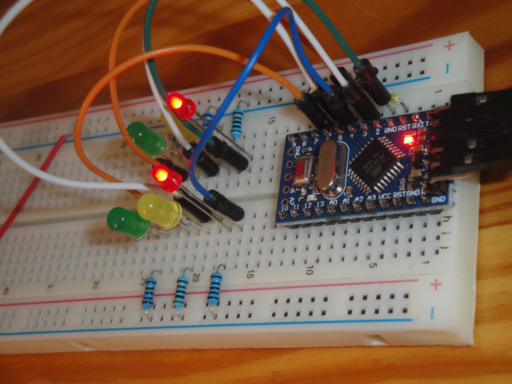
The Arduino Pro Mini is on the photos. It does not limit you, you can use any Arduino.
- Arduino Pro Mini (link) - I used this Arduino.
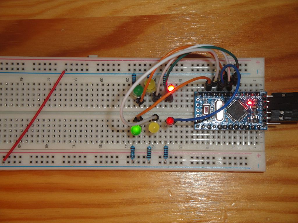
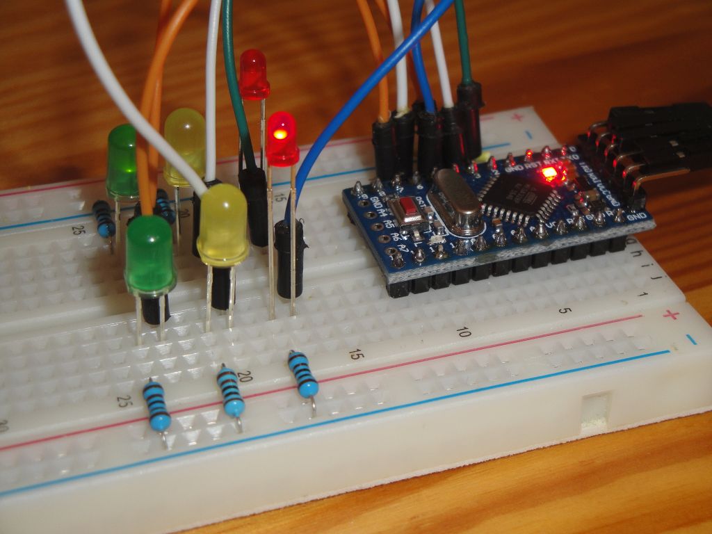
- Breadboard (link) - The components are plugged into the breadboard.
- 2x green, yellow and red LED - I chose the colors so as to resemble the lights on the traffic lights as much as possible. The yellow LED is a replacement for the orange color.
- 6x resistor 1k - The resistor limits the current flowing through the LED. Because we use high-luminous LEDs, a couple of milliamps are enough for us.
Traffic light
Our example simulates two semaphores. There are three lights on both. The three lights take care the cars do not crashed on the crossing. So one semaphore has the green light and the other has the red. At regular intervals, lights on traffic lights exchange.
A typical traffic light in Slovakia operates as follows. The traffic lights illuminate for 10-20 seconds green. It switches to orange and then to red. Then the red color shines for 10-20 seconds. Simultaneously with red color turns orange. Then both colors go out and the green color turns on. This is repeated over and over again. At the second traffic lights, the colors are shifted. Always the red color is on one traffic light and the green color is on the other.
Sequencer
Sequencers are very simple tools. At regular intervals, they send the requested value to the output. In our case, we will create a sequencer to simulate the previous example. At 1 s intervals, the LEDs are turned on or off. The sequencer has the advantage that if the program requirements change, the program itself does not need to change and only the sequence changes.
The sketch
I wrote three sketches. Two serve to test the circuit, and the third is to simulate a semaphore.
sequencer_traffic_light_01
The first program is used to test the circuit. Gradually turns on each LED. If all lights up, you are connected properly.
int leds[] = {2, 3, 4, 5, 6, 7};
int step = 0;

void setup() {
  for (int i = 0; i < 6; i++)
    pinMode(leds[i], OUTPUT);
}

void loop() {
  for (int i = 0; i < 6; i++)
    digitalWrite(leds[i], i == step ? HIGH : LOW);
  step++;
  step %= 6;
  delay(1000);
}
sequencer_traffic_light_02
The second program serves to test the circuit and the sequencer. The sequencer is created in the Sequencer class. It has only two functions. In the constructor, we mark the sequence data and in the function next, we advance each time in sequence and set the LED to HIGH or LOW. Note the LEDs on which Arduine pins are connected. These are pins 2, 3, 4, 5, 6 and 7. Why did I choose these pins? Because all these pins are on port D and I can control them by assigning a value directly to the port.
int leds[] = {2, 3, 4, 5, 6, 7};

//  222111xx
//  GYRGYR
const char PROGMEM sequence[] = {
  0b00000100,
  0b00001000,
  0b00010000,
  0b00100000,
  0b01000000,
  0b10000000,
};
const int sequence_length = sizeof(sequence) / sizeof(char);

class Sequencer {
    char *data;
    int len;
    int pos;

  public:
    Sequencer(char *_data, int _len)
      : data(_data), len(_len), pos(0)
    {}

    void next() {
      char b = pgm_read_byte(&data[pos]);
      PORTD = b;
      pos++;
      if (pos == len)
        pos = 0;
    }
};

Sequencer seq(sequence, sequence_length);

void setup() {
  for (int i = 0; i < 6; i++)
    pinMode(leds[i], OUTPUT);
}

void loop() {
  seq.next();
  delay(1000);
}
sequencer_traffic_light_03
The third program is the simulation of the lights at the crossroad. The previous example has been timed with function delay due to clarity. Now we can make our program as efficient as possible and use timer1 for timing. Using the calculator we set the timer to 1 Hz (every 1000 ms), and the function next in the Sequencer class will be called from the TIMER1_COMPA_vect interrupt.
int leds[] = {2, 3, 4, 5, 6, 7};

//  222111xx
//  GYRGYR
const char PROGMEM sequence[] = {
  0b10000100, // red, green
  0b10000100,
  0b10000100,
  0b10000100,
  0b10000100,
  0b10000100,
  0b10000100,
  0b10000100,
  0b10000100,
  0b10000100,
  0b01000100, // red, orange
  0b01000100,
  0b00100100, // red, red
  0b00101100, // red+orange, red
  0b00110000, // green, red
  0b00110000,
  0b00110000,
  0b00110000,
  0b00110000,
  0b00110000,
  0b00110000,
  0b00110000,
  0b00110000,
  0b00110000,
  0b00101000, // orange, red
  0b00101000,
  0b00100100, // red, red
  0b01100100, // red, red+orange
};
const int sequence_length = sizeof(sequence) / sizeof(char);

class Sequencer {
    char *data;
    int len;
    int pos;

  public:
    Sequencer(char *_data, int _len)
      : data(_data), len(_len), pos(0)
    {}

    void next() {
      char b = pgm_read_byte(&data[pos]);
      PORTD = b;
      pos++;
      if (pos == len)
        pos = 0;
    }
};

Sequencer seq(sequence, sequence_length);

void setupTimer1() {
  noInterrupts();
  // Clear registers
  TCCR1A = 0;
  TCCR1B = 0;
  TCNT1 = 0;

  // 1 Hz (16000000/((15624+1)*1024))
  OCR1A = 15624;
  // CTC
  TCCR1B |= (1 << WGM12);
  // Prescaler 1024
  TCCR1B |= (1 << CS12) | (1 << CS10);
  // Output Compare Match A Interrupt Enable
  TIMSK1 |= (1 << OCIE1A);
  interrupts();
}

void setup() {
  for (int i = 0; i < 6; i++)
    pinMode(leds[i], OUTPUT);
  setupTimer1();
}

void loop() {
}

ISR(TIMER1_COMPA_vect) {
  seq.next();
}
Source code
The source code is located on the GitHub server.
Video
12.09.2017