For beginners: NPN transistor as a switch
Zápisník experimentátora
Electronic devices are becoming increasingly complex and complex. This means for beginners it is difficult to get a minimum level of knowledge without having to study complex things. In this article, we look at the very beginning. We will show what the NPN transistor can be used for.
Transistor is a basic building block in microcontrollers. Although we use them indirectly in Arduino, it's good to know how they work. In certain situations, it is not sufficient to use a normal I / O pin. But before we connect the transistor to Arduino, we'll explain how it works. When I was preparing this article, I wondered how to write it as easily as possible. The electronic circuit we will study in this article does not have components designed randomly. The values of the resistors used can be calculated using several formulas. On the other hand, the use of formulas is almost never necessary. Once you calculate your first resistor to the LED, you will never calculate it again. You just remember that when you use a blue LED and add a 1k resistor to it, enough current will flow through it to make the diode shine nicely.
And exactly the same it also works with transistors. In most cases, you will use the same type of transistor with the same resistor values. Therefore, this article focuses more on experimenting. We will show how to manage a transistor in a basic circuit with a common emitter. We will show in which places we can measure interesting values of tension. You can measure them with a multimeter or with Arduino. And if you want to know more details, we'll discuss it later with a separate article.
Parts list
We need these parts.
- Breadboard {linkBreadboard}
- Power supply {linkPowerSupply}
- Resistor 1k, 120k {linkR}
- LED diode {linkLED}
- NPN Transistor BC547B {linkTransistor}
- Connecting wires
- Arduino {linkArduino}
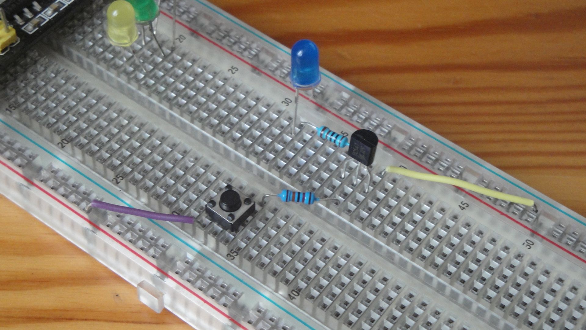
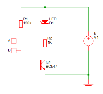
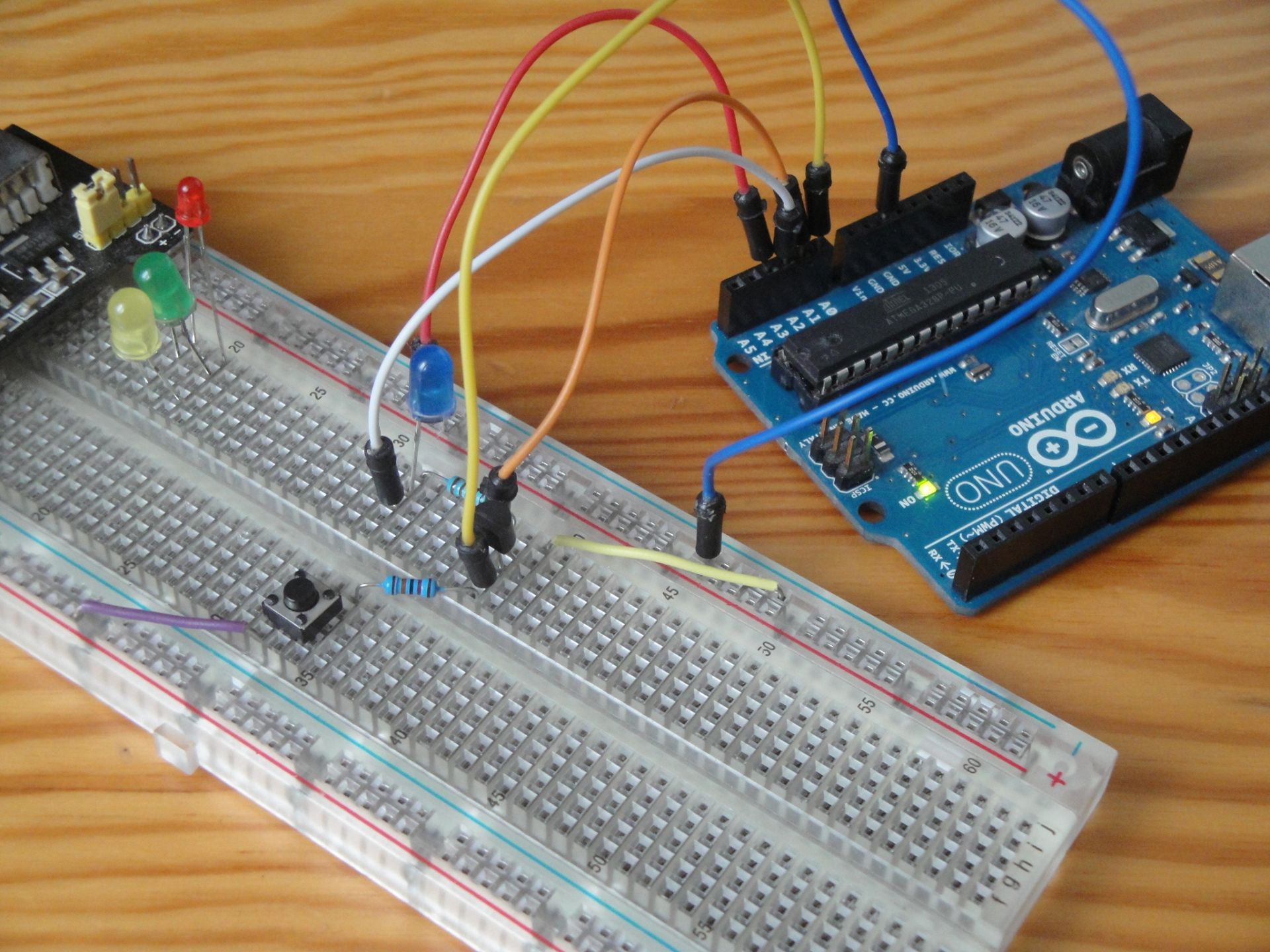
The figure shows an electronic circuit connected according to the scheme on the breadboard. A microswitch and a resistor R1 are exchanged over to the schematic, but this has no effect on the circuit operation. You see there two branches that are on one side connected to the power supply and on the other hand they are connected to the transistor. The first branch is a resistor R1 (120k) and a microswitch. It is only marked in the diagram with points A and B. This is done so that you can remove it at any time and replace the place with a wire to the power source or GND. If you measure anything in the electronic circuit with a multimeter, it is more convenient to have it connected without a microswitch. On the other hand, when you experiment with the circuit, it is more convenient to press the microswitch. The second branch consists of a LED and a resistor R2 (1k). The LED lights up when the microswitch is pressed.
The transistor has three inputs:
- C - Colector
- B - Base
- E - Emitor
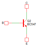
Now I will greatly simplify the operation of the NPN transistor. Such a connection is called a common emitter connection. The current between the collector and the emitter only flows when a significantly less current flows into the base. Imagine a huge water pipe that has a small water tap on top. When you turn a small tap, a large pipe opens and the water rolls through. The ratio between current to base and current through the collector-emitter is called the DC current gain hFE and, for example, with the BC547B it has a minimum value of 200. This value is quite different for each transistor piece produced, but we can say that we need 200 times less current to control current between collector and emitter.
And now is a good time for some simple experiments.
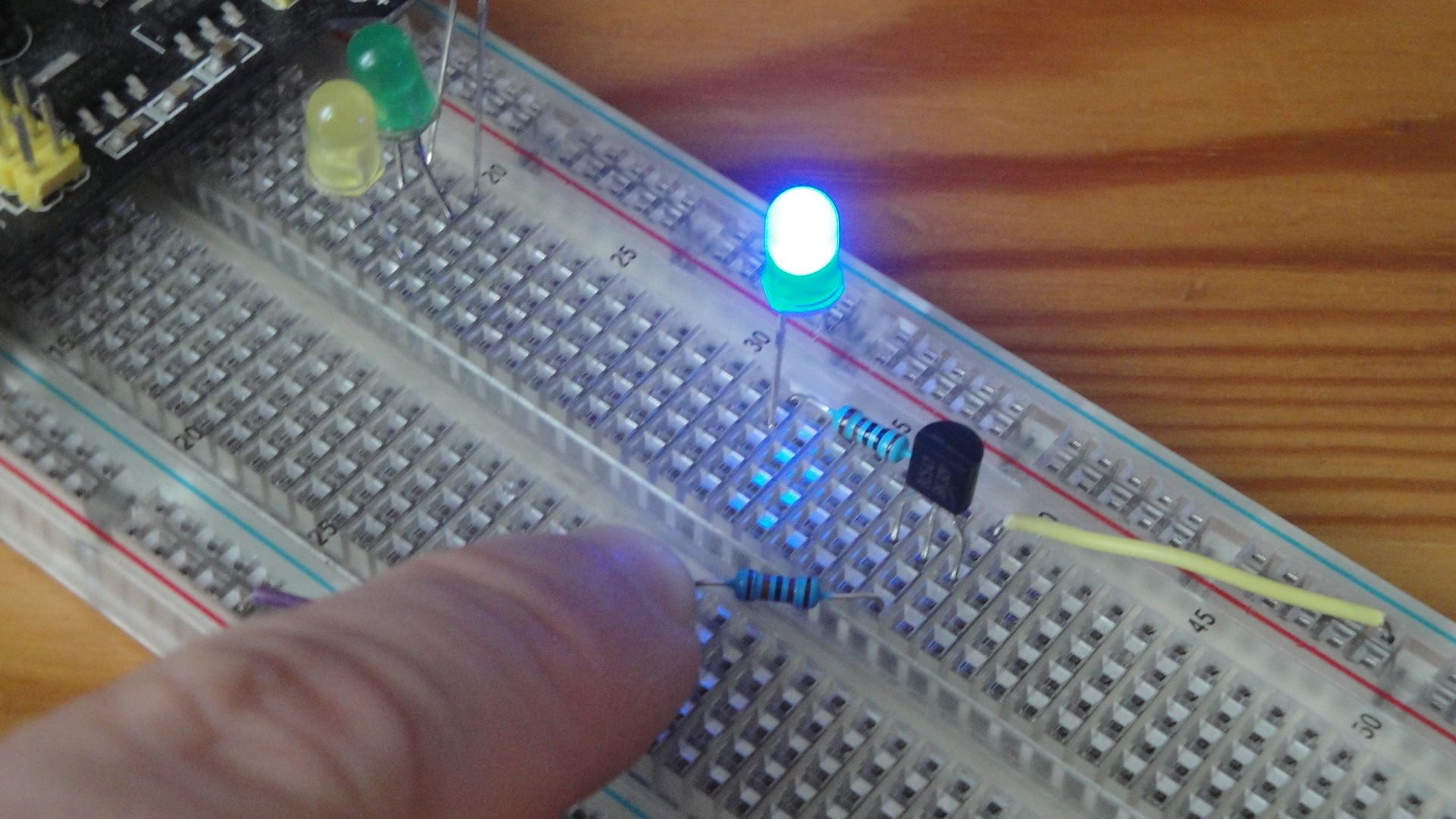
- When contacts A and B are not connected, the LED is off.
- Connect the A and B contacts. The LED will be bright. It depends on which LEDs you use. The blue LED will be bright, but other colors may not be so bright. Much also depends on the surface of the LED. Those with transparent material can shine less because more light is released out. Therefore, the choice of LED needs to be adapted to your needs.
- Try to connect contacts A and B with your finger. If the LED does not light up, try to wet your finger. The LED will be lit but the brightness will not be as strong.
- Leave contacts A and B unconnected and watch what happens when you connect emitter E and collector C on the transistor. The LED will be bright.
- Connect contacts A and B (LED will be lit) and then connect base B to the transistor and GND. The LED goes out.
This set of experiments illustrates the basic principles of transistor work. A small current (between base and emitter) controls a large current (between collector and emitter). Sometimes we say that the flow into the base has been amplified. And, to put it simply, we can say that the enhancement is constant. In the example we use transistor BC547B. The current through the collector is approximately 200 times greater than the current through the base. This is true only if it is not limited to a lower value by resistor R2 in the collector, as is the case here.
Based on the previous paragraph, we can say that if you remove resistor R2, the current through the LED will be small enough so that the LED does not burn. Quietly remove resistor R2 and watch what happens. The LED will be lit. If you have a multimeter, measure the current between the LED and the collector. You should measure less than 20 mA. The exact value will vary for each transistor you use. If you have many unused LEDs, sacrifice one and plug it between Vcc and GND. It burns instantly because there will not be a current limiting transistor gain.
When designing a power circuit with a transistor, you must first know exactly what you want to achieve.
- Does the transistor work as a switch and should it be completely off or on in states?
- Or is the transistor supposed to act as an analog amplifier and only allow more or less current?
You've tried both cases in this experiment. When you connected contacts A and B, the transistor was completely opened. However, thanks to the internal resistance, this is not identical to that of the two metal contacts. The result of internal resistance is that you measure a small drop in voltage between the collector and emitter. When you connected contacts A and B with a wet finger, you created an analog amplifier. The resulting LED brightness depended on how damp your skin was and how strongly you pressed the contacts.
One of the complications in designing a transistor electrical circuit is that you never know the exact transistor gain. Unlike resistors, where you are within 1%, it is very difficult to produce transistors at a precise value. In the case of transistor BC547, the gain is in the range of 110-800. Therefore, the production works by making, measuring and then dividing the transistors into three groups A, B and C. However, there is a large dispersion between the amplifier in one group. The designer must therefore design an electrical circuit to accommodate any transistor that is used in the electrical circuit.
Arduino as a multimeter
The theory is over and so we can have some fun with Arduino. Because Arduino has 6 analog inputs and in the IDE we can find the output in the form of a graph to which the output through the serial port is transformed, we can use Arduino as a multimeter. We can connect individual inputs to suitable places and measure the voltage there. Try the following connection and upload adc6_plotter to Arduino. Inputs are connected to places that were mentioned in the article. Watch the IDE Plotter and see what happens when you perform previous experiments.
const double vref = 5.0;

void setup() {
  Serial.begin(115200);

}

void loop() {
  double a0 = analogRead(A0) * vref / 1023.0;
  double a1 = analogRead(A1) * vref / 1023.0;
  double a2 = analogRead(A2) * vref / 1023.0;
  double a3 = analogRead(A3) * vref / 1023.0;
  double a4 = analogRead(A4) * vref / 1023.0;
  double a5 = analogRead(A5) * vref / 1023.0;

  Serial.print(a0);
  Serial.print(",");
  Serial.print(a1);
  Serial.print(",");
  Serial.print(a2);
  Serial.print(",");
  Serial.print(a3);
  Serial.print(",");
  Serial.print(a4);
  Serial.print(",");
  Serial.print(a5);
  Serial.println("");

  delay(100);
}
Source code
The source code is located on GitHub.
Video
In the video, you can see how the transistor works. The video is in Czech. It's not my video, but who cares about the theory of electrons that jump between layers of material, this video will find very well explained.
Video
06.07.2019