Debugging the contents of the registry from the microcontroller
Zápisník experimentátora
Even as Arduino users, you know that there are many system registries in the microcontroller. By setting individual bits in the register, you control the behavior of various peripherals. In front of Arduino users, the registers are packed into functions. When you examine the microcontroller more deeply, you will find that you have to adjust them from time to time. Then you may want to display the individual bits as you find them in the microcontroller datasheet.
I am preparing an article about PWM modes of a microcontroller in Arduino. In addition to the usual 8-bit PWM, it can make 9, 10 to 16 bit PWM on timer 1. You turn on 8-bit PWM using the analogWrite function. It internally sets the necessary registers to achieve the required function. When you dive into the source code of the function (1, 2), you will find there a lot of conditional code, the meaning of which is not always completely clear. This is because the function takes into account a larger number of microcontrollers, which set the same function using different bits in different registers. In order to display the bit settings as you see them listed in the datasheet, I wrote this source code.
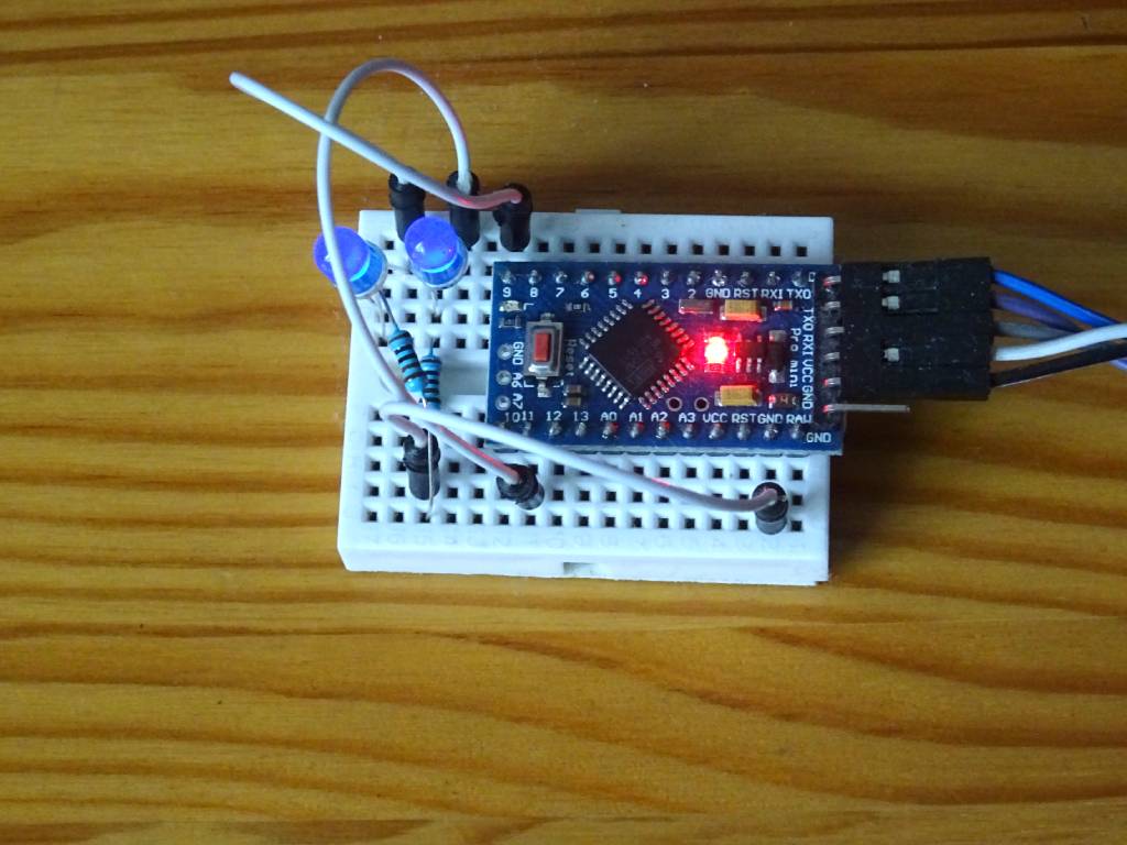
The electrical circuit is simple in this case. All you need is an Arduino and 2 LEDs and 2 resistors. Connect them to pins 9 and 11 to be on timers 1 and 2. I usually use blue LEDs and 1k resistors. That's enough for the LED to glow but not blind your eyes at the same time.
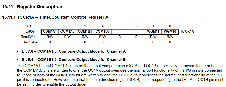
The following image is an example from the ATmega328P microcontroller datasheet in Arduino. The TCCR1A register allows you to set several different bits that affect the behavior of the timer. So that we don't have to constantly check that the bits are set correctly, I wrote this source code, which formats the bit settings in the register and writes them to the serial port, as you can see in the datasheet. An example of the statement can be found at the end of the article.
The sketch
The program consists of two files.
- dump.h
- arduino_pwm_modes01.ino
dump.h
In the source code, you see the class DumpRegister and several macros and functions that serve to ensure the desired functionality so that the programmer does not do much. The class is used to store register names and individual bits. The class has many parameters in the constructor, and to simplify the code, the DREG macro is used, which performs magical operations on variables and turns them into text strings that enter the constructor as parameters. The combination of the << operator and another macro _() is used to list the current registry setting.
#define RESERVED -1

class DumpRegister {
    int reg;
    const char *regname;
    int bits[8];
    const char *bitnames[8];

  public:
    DumpRegister(int _reg, const char *_regname,
                 int b7, int b6, int b5, int b4, int b3, int b2, int b1, int b0,
                 const char *bn7, const char *bn6, const char *bn5, const char *bn4,
                 const char *bn3, const char *bn2, const char *bn1, const char *bn0)
      : reg(_reg),
        regname(_regname)
    {
      bits[7] = b7; bitnames[7] = bn7;
      bits[6] = b6; bitnames[6] = bn6;
      bits[5] = b5; bitnames[5] = bn5;
      bits[4] = b4; bitnames[4] = bn4;
      bits[3] = b3; bitnames[3] = bn3;
      bits[2] = b2; bitnames[2] = bn2;
      bits[1] = b1; bitnames[1] = bn1;
      bits[0] = b0; bitnames[0] = bn0;
    }

    friend Print& operator << (Print &obj, DumpRegister &d);
};

Print& operator << (Print &obj, DumpRegister &d) {
  obj.print(d.regname);
  obj.print("=");
  int v = *(volatile uint8_t *)(d.reg);
  obj.print(v, BIN);
  obj.print(":");
  for (int i = 7; i >= 0; i--)
    if (d.bits[i] != -1 && v & (1 << i)) {
      obj.print(" ");
      obj.print(d.bitnames[i]);
    }
  obj.println("");
  return obj;
}

#define DREG(var, b7, b6, b5, b4, b3, b2, b1, b0) \
  DumpRegister dr_##var(&var, #var, b7, b6, b5, b4, b3, b2, b1, b0, #b7, #b6, #b5, #b4, #b3, #b2, #b1, #b0);

#define _(var) dr_##var

#define DUMPVAL(var)          \
  {                           \
    Serial.print(#var);       \
    Serial.print("=");        \
    Serial.println(var, BIN); \
  }
arduino_pwm_modes01.ino
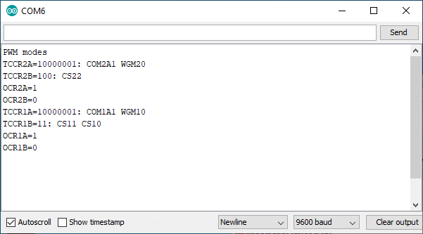
In this source code, you can see how to use the previous source code. Using the DREG macro, we define the individual registers and bits that interest us according to the datasheet. In this case, these are the registers for timers 1 and 2. We set some values for them and then we can write them to the serial port using the << operator and the _() macro.
This way you can do it with any register and conveniently find out the bit settings that Arduino does. You can also find out if your bit setting is in the registry as you imagined. Logical operations in the registry have already bothered many experienced programmers, and this is a form of debugging that will help you with Arduino, because you do not have a debugger available in the Arduino development environment to check the settings with it.
#include "dump.h"

DREG(TCCR2A, COM2A1, COM2A0, COM2B1, COM2B0, RESERVED, RESERVED, WGM21, WGM20)
DREG(TCCR2B, FOC2A, FOC2B, RESERVED, RESERVED, WGM22, CS22, CS21, CS20)
DREG(TCCR1A, COM1A1, COM1A0, COM1B1, COM1B0, RESERVED, RESERVED, WGM11, WGM10)
DREG(TCCR1B, FOC1A, FOC1B, RESERVED, RESERVED, WGM12, CS12, CS11, CS10)

void setup() {
  pinMode(11, OUTPUT); // TIMER2A
  pinMode(9, OUTPUT);  // TIMER1A
  analogWrite(11, 1);  // minimal PWM value
  analogWrite(9, 1);   // minimal PWM value

  Serial.begin(9600);
  Serial.println("PWM modes");

  // TIMER2
  Serial << _(TCCR2A);
  Serial << _(TCCR2B);
  DUMPVAL(OCR2A)
  DUMPVAL(OCR2B)

  // TIMER1
  Serial << _(TCCR1A);
  Serial << _(TCCR1B);
  DUMPVAL(OCR1A)
  DUMPVAL(OCR1B)
}

void loop() {
}
Source code
The source code is located on the GitHub server.
Video
29.05.2020