Timer1 - 10-bit PWM and potentiometer
Zápisník experimentátora
Hierarchy: Časovač (timer)
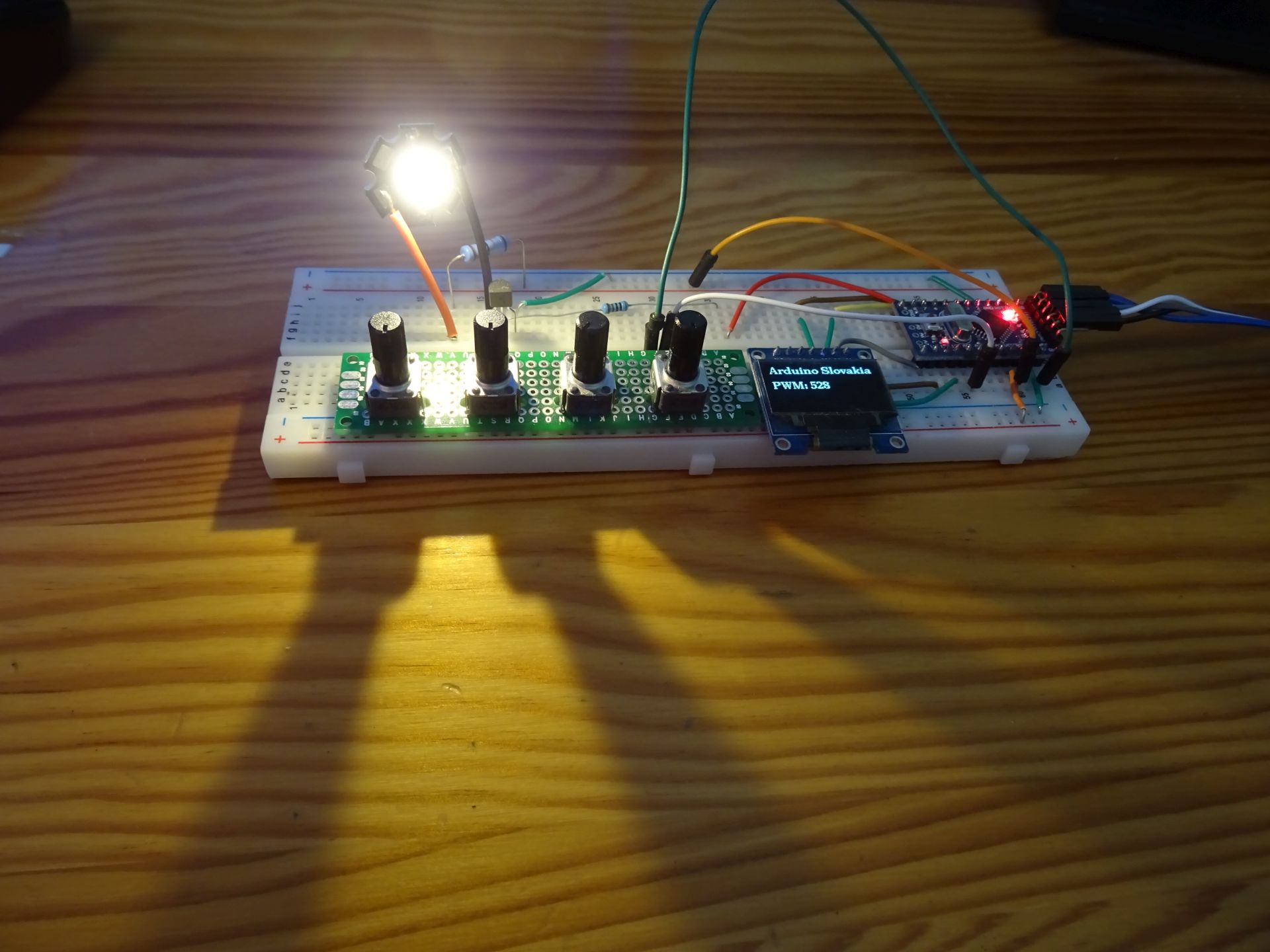
In this article, we will show how to use the 10-bit mode on the timer1. We will use one potentiometer so that we can comfortably set the value of the duty cycle. Analog measurement provides 10-bit resolution, so we don't have to do any conversion. The measured value of the analog input is displayed on the OLED display.
Parts list
We need these parts.
- Breadboard {linkBreadboard}
- Resistor 100R, 10R, 1k {linkR}
- LED diode {linkLED}
- NPN Transistor BC547B {linkTransistor}
- OLED display {linkOLED}
- Wires
- Potentiometer
- Arduino {linkArduino}
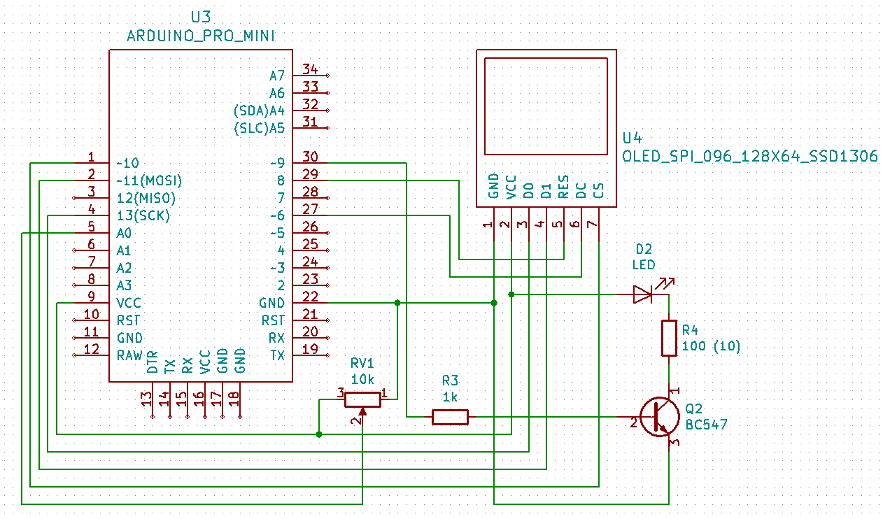
I have explained a similar electrical circuit several times. In this case, pin 9, on which the output of timer 1 is located, is important. It is connected to an NPN transistor that controls the brightness of a 1W LED. I use a 100R resistor so that I can photograph a LED without crazy artefacts. This ensures that the current through the LED is only 20 mA, which is enough value for the LED to be photographed.
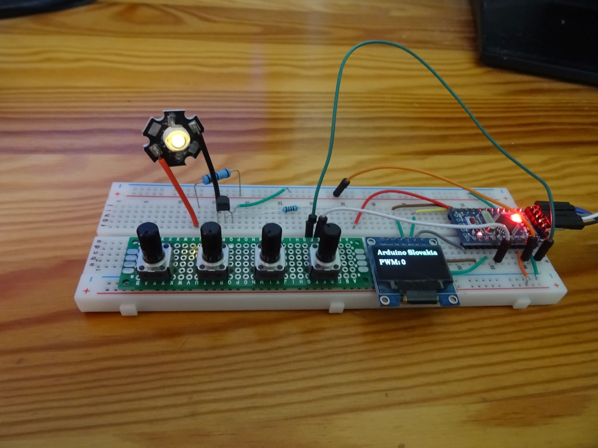
The OLED display uses the U8g2 library. Depending on the display version, it is necessary to adjust the connection and select a suitable constructor. If you are unsure, use a slower version with less memory consumption, but you can connect to any pins. Here is a wiring that uses hardware SPI and the remaining pins can be connected arbitrarily.
The sketch
The program is simple. We set timer 1 mode 7, which is 10-bit, Fast PWM. And instead of the analogWrite function, we use writing the value to the OCR1A register. I do analog measurement 64 times and average it to achieve a better smoothing of the measured value. See also the accompanying video, in which I show that such averaging is necessary on breadboard and that imperfect joints on breadboard can cause problems in analog measurement.
#include <U8g2lib.h>

U8G2_SSD1306_128X64_NONAME_1_4W_HW_SPI u8g2(U8G2_R0, /* cs=*/ 10, /* dc=*/ 6, /* reset=*/ 8);

#define ledPin 9

volatile int pwmvalue = 0;
char buff[20];

// Mode 7: 10-bit Fast PWM
void setupTimer1() {
  pinMode(ledPin, OUTPUT);
  TCCR1A = (1 << WGM11) | (1 << WGM10) | (1 << COM1A1);
  TCCR1B = (1 << WGM12) | (1 << CS11) | (1 << CS10);
  OCR1A = 1;
}

void setup() {
  u8g2.begin();
  u8g2.setFont(u8g2_font_ncenB10_tr);

  setupTimer1();
}

void drawInfo() {
  int y = 12;
  u8g2.firstPage();
  do {

    u8g2.drawStr(0, y, "Arduino Slovakia");
    sprintf(buff, "PWM: %d", pwmvalue);
    u8g2.drawStr(0, y * 3, buff);
  } while ( u8g2.nextPage() );
}

void loop() {
  long v = 0;
  for (int i = 0; i < 64; i++)
    v += analogRead(A0);
  pwmvalue = v / 64;
  OCR1A = pwmvalue;
  drawInfo();
}
Source code
The source code is located on the GitHub server.
20.07.2020