Transistor
Page
Stránky / Súčiastky ku Arduinu /
The transistor is the basic building block of any electronic device. Integrated circuits consist mainly of transistors. The basis of the transistor is several layers of semiconductor transitions. Usually these are two PN transitions located very close together. This would seem to indicate that the transistor is two diodes together, but such an analogy cannot be used because the two PN layers are so close together that they interact. This is not possible with two diodes.
Basic types of transistors
Transistors are divided into:
- Bipolar - The transistor is controlled by a current flowing into the base. The electrodes are designated as collector, base, and emitter.
- Unipolar - Transistor is controlled by gate voltage. The electrodes are labeled as drain, base and gate.
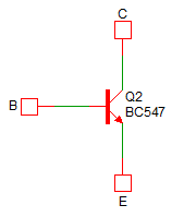
Bipolar transistor
The transistor has three inputs:
- C - Collector
- B - Base
- E - Emitter
For beginners
For beginners: NPN transistor as a switch
Electronic devices are becoming increasingly complex and complex. This means for beginners it is difficult to get a minimum level of knowledge without having to study complex things. In this article, we look at the very beginning. We will show what the NPN transistor can be used for.
For Beginners: Delayed Switch-off
We will build on the previous article on NPN transistors. Here, we have learned that the transistor current gain causes a very small current across the transistor base to generate much larger current between the collector and emitter. By adding a capacitor to the electrical circuit, we can change this circuit to a delayed switch-off.
Arduino
Arduino and bipolar transistor as a switch
In this article, we will explain how we can strengthen the Arduino output pin using a transistor. The purpose of the article is not to explain the theory of transistor operation. We will limit ourselves to the minimum necessary. As an example, we use a high-light LED, which can flow 350 mA. This is far beyond the possibilities of Arduino. We will be able to control it with a transistor.
LED dimmer with timer
The dimming of LED can be programmed in several ways. In this article, we will focus on not having a function delay in the program that hinders the running of the program so that it can no longer do anything else. Nor will we use the function millis to eliminate program delays. Instead, we will use the timer, which we set to give us a signal at regular intervals when we should do the next dimming step.
Timer1 - 10-bit PWM and potentiometer
In this article, we will show how to use the 10-bit mode on the timer1. We will use one potentiometer so that we can comfortably set the value of the duty cycle. Analog measurement provides 10-bit resolution, so we don't have to do any conversion. The measured value of the analog input is displayed on the OLED display.
20.07.2020