8x PWM in one Arduino
Zápisník experimentátora
Hierarchy: Časovač (timer)
Arduino Uno has 6 PWM channels on pins 3, 5, 6, 9, 10 and 11. In this article we will show that this may not be the final count. But we need to replace the hardwired PWM with our own code. In this example, we use a timer to generate an interrupt at a high enough frequency to be able to simulate PWM on eight channels at a time.
Used parts
To create an animation we can use:
- Arduino Pro Mini (link) - I used it because it will fit into the smallest breadboard.
- Mini Breadboard (link) - The smallest sold breadboard. I used two and be careful that there are two modifications of this breadboard. Those that have small protrusions can be nicely connected to each other.
- Converter CP2102 USB to Serial (link) - The converter is used to program the Arduino.
- Board with resistors and LEDs (link) - Because I have made some of these boards, I used it so I do not have to complicately connect 8 LEDs and 8 resistors to the Arduino pins. But you can also use resistors and LEDs directly, just be careful not to exceed the maximum current on the pin. Therefore, use resistors from 330 to 1000 ohms.
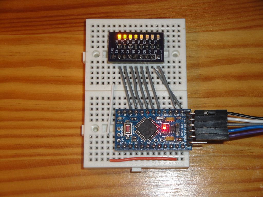
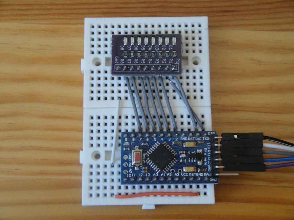
Everything is connected according to the following picture. The LEDs are connected to the pins RX (0), TX (1), 2-7 and the GND connection is still visible on my LED board with two wire links to Arduino. Arduino Pro Mini has a GND on the other side, so I could use a single jumper, but then it would be badly photographed.
RX and TX are mutually switched because the 8-bit number bit is displayed by direct write to the PORTD register, and we need to have the pins sorted in the same way as the bits in the register.
Programming
In order to create the effect of the different brightness of all diodes, we must properly turn these LEDs on and off, and we need to do so quickly so that the human eye does not see blinking but different intensity of light. We need a frequency of at least 25 Hz for the smallest continuous image, but the smooth impression is better 50-75 Hz. And because we need 256 shades in each window of our animation, we need a resulting frequency of 75x256 = 19200 Hz. Round it up to 20 kHz.
At this frequency, we need to call an interrupt that sets the brightness on all diodes by turning the diode on or off. The longer the diode is on, the more bright it will be. A simplified scheme with three boxes of 10 levels of brightness shows us how the four diodes are flashing. This is exactly the same at our 20 kHz frequency.
123456789012345678901234567890
x         x         x
xx        xx        xx
xxxxx     xxxxx     xxxxx
xxxxxxxxxxxxxxxxxxxxxxxxxxxxxx
That is the whole essence of the effect. Now let's look at the source code.
At the beginning, two macros can be defined or denoted. These do not affect the resulting animation. It only affects writing to the port quickly or using digitalWrite. And they affect whether to replace the Arduino main function by ours to make sure that the Arduino core does not set up registers by default. Both choices essentially minimize the resulting code to a minimum. And to the Arduino haters, if any, will show that Arduino can accessed ports directly and that we understand how the linker works.
#define DIRECT_WRITE
#define FAKE_MAIN
The variable counter is used to monitor the brightness position in a single window. It can contain 0-255 values. By the value, I decide whether the diode will light up or not. And I have a brightness value for each diode in the variable light. Each value is twice the previous one to take into account the nonlinear behavior of the human eye.
uint8_t counter = 0;
uint8_t light[] = {1, 2, 4, 8, 16, 32, 64, 128};
I have this code completely generated in my CTC timer calculator. The set frequency is 20 kHz and the calculator has taken care of the appropriate registers setting. I use timer1.
void setupTimer() {
  noInterrupts();
  TCCR1A = 0;
  TCCR1B = 0;
  TCNT1  = 0;

  OCR1A = 99; // 20000 Hz
  TCCR1A |= 0;
  TCCR1B |= (1 << WGM12);
  TCCR1B |= (0 << CS12) | (1 << CS11) | (0 << CS10);
  TIMSK1 |= (1 << OCIE1A);
  interrupts();
}
In the function setup, I set which pins are to be output. Thanks to that all the pins are on port D, we can also use the direct register write.
void setup() {

#ifdef DIRECT_WRITE
  DDRD = 0b11111111;
#else
  for (uint8_t i = 0; i < 8; i++)
    pinMode(i, OUTPUT);
#endif
  setupTimer();
}
We do nothing in the function loop. All work is done by the interrupt handler. If we use a direct write in the register, we need to prepare all 8 bits in the auxiliary variable tmp. If the brightness for a particular LED is higher than the value in the variable counter, the diode will light up. Otherwise, it will be off. From this, we can deduce that the larger the number in light [i], the diode will shine brighter.
void loop() {
}

ISR(TIMER1_COMPA_vect) {

#ifdef DIRECT_WRITE
  uint8_t tmp = 0;
  for (uint8_t i = 0; i < 8; i++)
    if(light[i] > counter)
      bitSet(tmp,i);
  PORTD = tmp;
#else
  for (uint8_t i = 0; i < 8; i++)
    digitalWrite(i, light[i] > counter ? true : false);
#endif

  counter++;
  counter = counter % 255;
}
Custom function main. This can be done because the linker is looking for compiled pieces of code sequentially, and if they are two with the same function name, it prefers the first and the other will ignore it. In this case, the first one is that we place in the code of our main program.
In the program, note one more interesting thing. It is the UCSR0B registry setting. We have to do this because Arduino bootloader modifies the behavior of the RX and TX pins, and we would not see our PWM on these two pins. Therefore, we will disconnect the two pins from the USART and get the desired behavior.
#ifdef FAKE_MAIN
int main(void) {
  UCSR0B = 0; // disable bootloader USART
  setup();
  while(1)
    loop();
return 0;
}
#endif
Source code
The source code is located on GitHub.
Video
The video is on YouTube.
15.04.2018