ESP8266 WiFi scanner
Zápisník experimentátora
Hierarchy: ESP8266
In this article we will scan WiFi networks using ESP8266. Based on a sample example, we will adjust the results to show on the 0.96 OLED display. In the past, I wrote a similar article on WiFi scanning, in which I used the Arduino MKR1000 board. The behavior of this program will be identical. Only the display of WiFi network information is customized to the display options.
Used parts
The following parts are used in the article:
- NodeMCU 0.9 (link) - But if you can, buy the version 1.0.
- 7pin 0.96 in SPI OLED 128x64 White (link) - It is essential that the display be marked as SPI. These are significantly faster than the I2C versions. They are sold in three color modifications. White, blue and two-color. The display has a voltage of 5 V.
- Breadboard (link) - I use three miniatures because NodeMCU 0.9 and the display does not get on a normal breadboard. Three minibreadboards have the advantage that you have plenty of space and you can simply connect the individual pins with wires.
OLED display
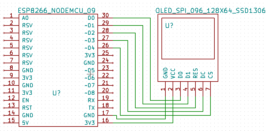
The connection between the pins is as follows.
| NodeMCU | OLED |
|---|---|
| D0 | D0 |
| D1 | D1 |
| D2 | RES |
| D3 | DC |
| D4 | CS |
| GND | GND |
| 3V3 | VCC |
Because this connection uses the SPI software control, I used the following constructor from the U8g2 library. You install the library through a library manager.
#include <U8g2lib.h>

U8G2_SSD1306_128X64_NONAME_F_4W_SW_SPI u8g2(U8G2_R0, /* clock=*/ D0, /* data=*/ D1, /* cs=*/ D4, /* dc=*/ D3, /* reset=*/ D2);
IDE
I tested all the connections in IDE 1.8.2. ESP8266 is installed in version 2.3.0.
Program (sketch)
I changed the program slightly from the original WifiScan.ino program. He listed the networks found on the serial port. I kept all of this, just added the OLED display and added a better encryption detection. The encryption recognition code is identical to the version of the MKR1000 program. You can find the complete version of the code at GitHub.
The setup function initializes the graphics for the OLED display, displays the program information and sets the appropriate WiFi mode.
void setup() {
  u8g2.begin();
  u8g2.setFont(u8g2_font_ncenB10_tr);

  u8g2.clearBuffer();
  u8g2.drawStr(0, 12, "Arduino Slovakia");
  u8g2.drawStr(0, 26, "WiFi Scanner");
  u8g2.sendBuffer();

  Serial.begin(115200);

  // Set WiFi to station mode and disconnect from an AP if it was previously connected
  WiFi.mode(WIFI_STA);
  WiFi.disconnect();
  delay(1000);

  Serial.println("Setup done");
}
Function messageBox serves for a more comfortable display of information texts on the serial port and display.
void messageBox(const char *message)
{
  Serial.println(message);
  u8g2.clearBuffer();
  u8g2.drawStr(0, 12, message);
  u8g2.sendBuffer();
}
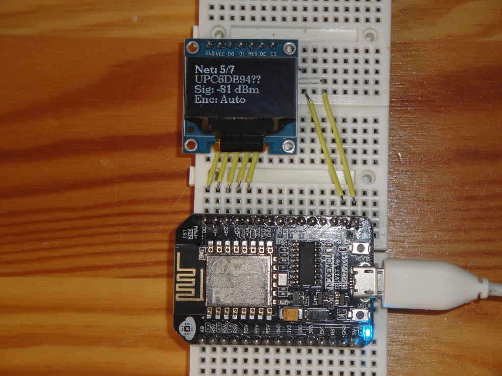
In the loop function, the list of WiFi access points is periodically scanned and displayed on the display. The screen has a resolution of 128x64, so we can use a larger resolution font. You can compare this display with the Nokia 5110 display that I used in the Arduino MKR1000 program.
void loop() {
  messageBox("scan start");

  // WiFi.scanNetworks will return the number of networks found
  int n = WiFi.scanNetworks(false,true); // false - async, true - hidden networks
  messageBox("scan done");
  if (n == 0)
    messageBox("no networks found");
  else
  {
    sprintf(draw, "%d netw. found", n);
    messageBox(draw);
    for (int i = 0; i < n; ++i)
    {
      // Print SSID and RSSI for each network found
      Serial.print(i + 1);
      Serial.print(": ");
      Serial.print(WiFi.SSID(i));
      Serial.print(" (");
      Serial.print(WiFi.RSSI(i));
      Serial.print(") ");
      Serial.println(getEncryptionType(WiFi.encryptionType(i)));

      // oled
      strcpy(ssid,WiFi.SSID(i).c_str());
      int dl=strlen(ssid);
      if(dl>2) { // hide some details
        ssid[dl-2]='?';
        ssid[dl-1]='?';
      }
      u8g2.clearBuffer();
      sprintf(draw,"Net: %d/%d",i+1,n);
      u8g2.drawStr(0, 12, draw);
      u8g2.drawStr(0, 26, ssid);
      sprintf(draw,"Sig: %d dBm",WiFi.RSSI(i));
      u8g2.drawStr(0, 40, draw);
      sprintf(draw,"Enc: %s",getEncryptionType(WiFi.encryptionType(i)));
      u8g2.drawStr(0, 54, draw);
      u8g2.sendBuffer();

      delay(2000);
    }
  }
  Serial.println("");
}
Source code
The source code is located at GitHub.
Video
Video is located at YouTube.
11.07.2017