CTC timer in the ATmega2560 microcontroller
Zápisník experimentátora
Hierarchy: Časovač (timer)
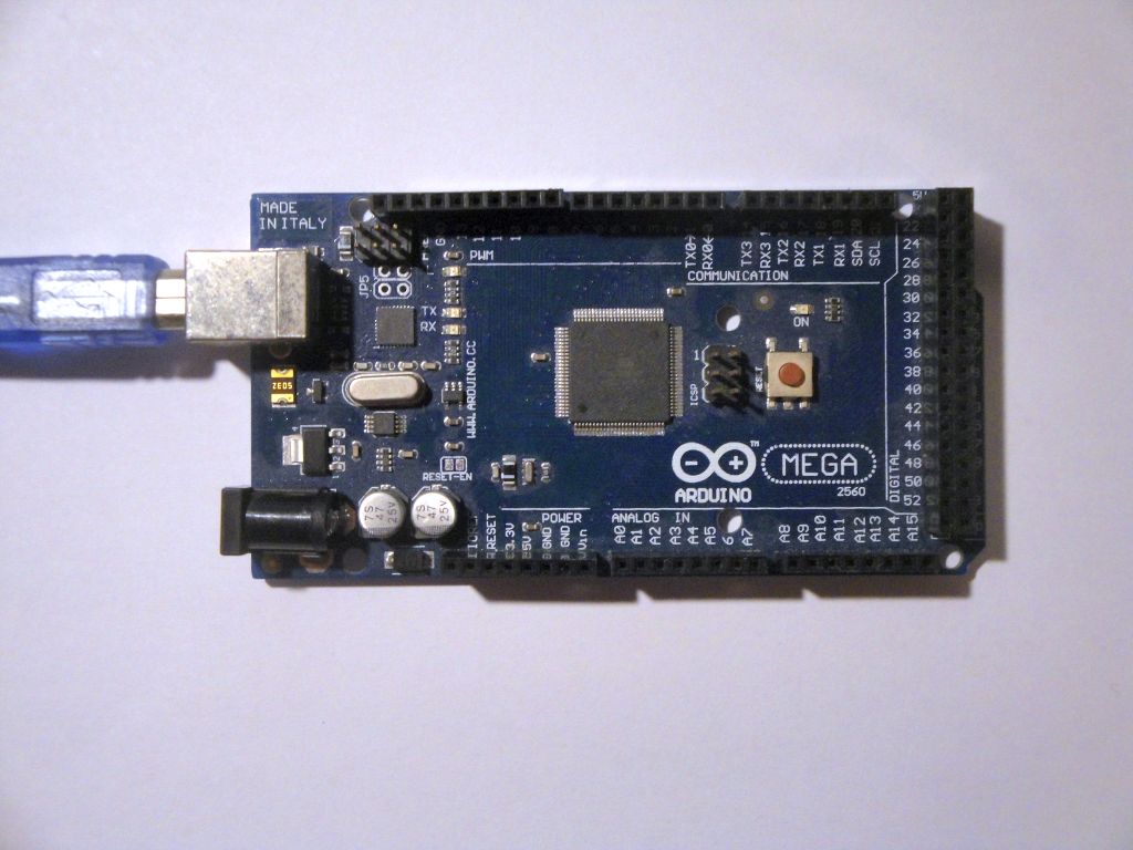
The ATmega2560 microcontroller is part of the Arduino Mega 2560 board. It has more pins and its authors have added more timers. It includes two 8-bit and four 16-bit timers. In this article, we look at timers from a CTC mode viewpoint. We will use the online calculator to generate the programs.
Timers
The first three timers are identical to ATmega328P.
- Timer0 - 8-bit.
- Timer1 - 16-bit.
- Timer2 - 8-bit.
In addition, three additional timers are added, which are an exact copy of the timer1.
- Timer3 - 16-bit.
- Timer4 - 16-bit.
- Timer5 - 16-bit.
Examples
For each timer I wrote a sample program that flashes with an internal LED at 1 Hz. In the examples, you will see that the 8-bit timer has to be set to a higher frequency and then you need to add an internal divider to get the desired frequency. With a 16-bit timer, this is not necessary and the desired frequency can be set directly.
Example Timer0 - 8-bit
#define ledPin 13
volatile int divider=0;

void setupTimer0() {
  noInterrupts();
  // Clear registers
  TCCR0A = 0;
  TCCR0B = 0;
  TCNT0 = 0;

  // 100.16025641025641 Hz (16000000/((155+1)*1024))
  OCR0A = 155;
  // CTC
  TCCR0A |= (1 << WGM01);
  // Prescaler 1024
  TCCR0B |= (1 << CS02) | (1 << CS00);
  // Output Compare Match A Interrupt Enable
  TIMSK0 |= (1 << OCIE0A);
  interrupts();
}

void setup() {
  pinMode(ledPin, OUTPUT);
  setupTimer0();
}

void loop() {
}

ISR(TIMER0_COMPA_vect) {
  if(divider==0)
    digitalWrite(ledPin, digitalRead(ledPin) ^ 1);
  divider++;
  divider%=100;
}
Example Timer1 - 16-bit
#define ledPin 13

void setupTimer1() {
  noInterrupts();
  // Clear registers
  TCCR1A = 0;
  TCCR1B = 0;
  TCNT1 = 0;

  // 1 Hz (16000000/((15624+1)*1024))
  OCR1A = 15624;
  // CTC
  TCCR1B |= (1 << WGM12);
  // Prescaler 1024
  TCCR1B |= (1 << CS12) | (1 << CS10);
  // Output Compare Match A Interrupt Enable
  TIMSK1 |= (1 << OCIE1A);
  interrupts();
}

void setup() {
  pinMode(ledPin, OUTPUT);
  setupTimer1();
}

void loop() {
}

ISR(TIMER1_COMPA_vect) {
  digitalWrite(ledPin, digitalRead(ledPin) ^ 1);
}
Source code
The source codes are located on the GitHub server.
- timer0_1hz_digitalwrite
- timer1_1hz_digitalwrite
- timer2_1hz_digitalwrite
- timer3_1hz_digitalwrite
- timer4_1hz_digitalwrite
- timer5_1hz_digitalwrite
14.09.2017