CTC timer in ATtiny84 microcontroller
Zápisník experimentátora
Hierarchy: Časovač (timer)
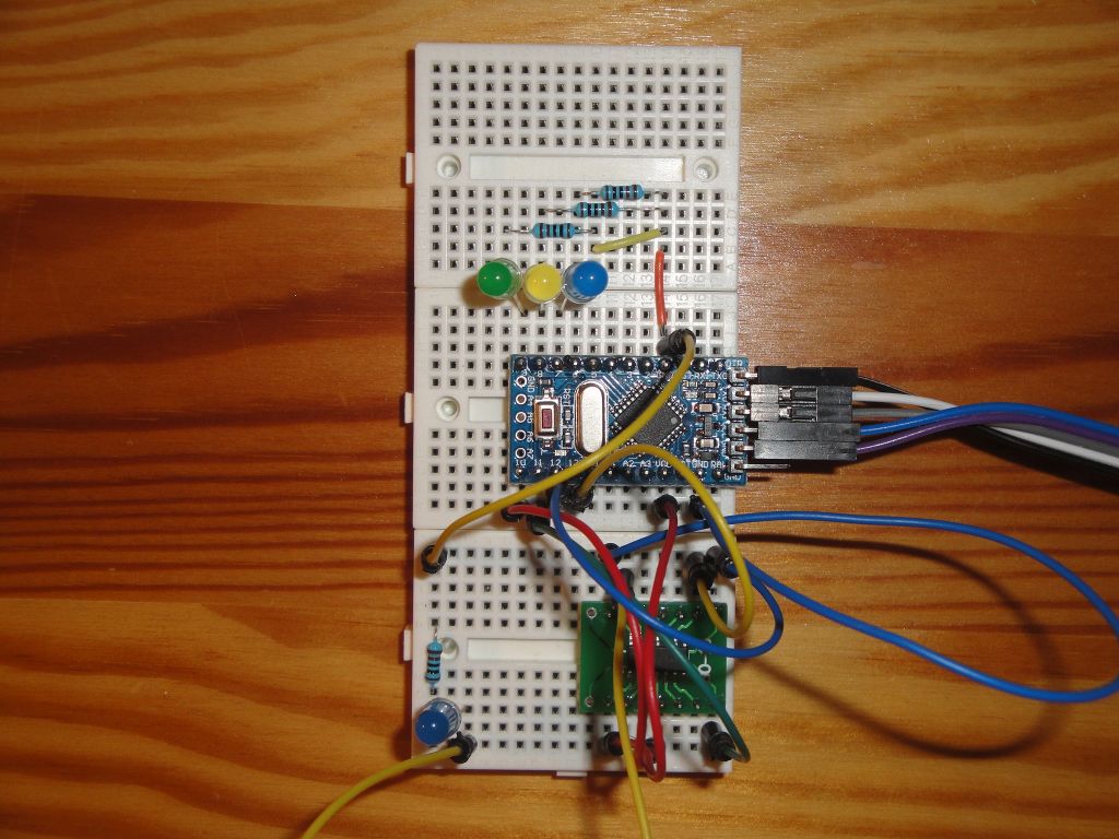
ATtiny84 contains two timers. One is 8-bit and the other is 16-bit. In this article, we look at timers from CTC mode. We will use the online calculator to generate the programs. I used the ATtiny84 microcontroller in the SMD version and therefore I had it on an adapter that can be inserted into the breadboard. I used the same connection as in the article ATtiny84 programming using the Arduino.
Used parts
When working with ATtiny84, I use Arduino for programming. Maybe it was a coincidence, but via USBasp I was stuck with ATtiny84's fuse. When using the Arduino I did not have this problem.
I wrote the source codes for 1 MHz and 8 MHz. I used the core https://github.com/SpenceKonde/ATTinyCore. There are two examples for each timer. They all blink with an LED that is connected to pin 10. Pin 10 is located on the microcontroller as shown on the picture. You must select the correct orientation (counterclockwise) when setting the board.
Timer0
Timer0 is an 8-bit counter. If we want to use it to create a lower frequency, we need to help yourself with an internal divider that is created using a variable divider. In this case, the interrupt frequency is 100 Hz and is adjusted to 1 Hz using the divider.
#define ledPin 10
volatile int divider=0;

void setupTimer0() {
  noInterrupts();
  // Clear registers
  TCCR0A = 0;
  TCCR0B = 0;
  TCNT0 = 0;

  // 100.16025641025641 Hz (1000000/((155+1)*64))
  OCR0A = 155;
  // CTC
  TCCR0A |= (1 << WGM01);
  // Prescaler 64
  TCCR0B |= (1 << CS01) | (1 << CS00);
  // Output Compare Match A Interrupt Enable
  TIMSK0 |= (1 << OCIE0A);
  interrupts();
}

void setup() {
  pinMode(ledPin, OUTPUT);
  setupTimer0();
}

void loop() {
}

ISR(TIMER0_COMPA_vect) {
  if(divider==0)
    digitalWrite(ledPin, digitalRead(ledPin) ^ 1);
  divider++;
  divider%=100;
}
Timer1
Timer1 is a 16-bit counter. This makes it easy to set low frequencies. In this case, the frequency is 1 Hz.
#define ledPin 10

void setupTimer1() {
  noInterrupts();
  // Clear registers
  TCCR1A = 0;
  TCCR1B = 0;
  TCNT1 = 0;

  // 1 Hz (1000000/((15624+1)*64))
  OCR1A = 15624;
  // CTC
  TCCR1B |= (1 << WGM12);
  // Prescaler 64
  TCCR1B |= (1 << CS11) | (1 << CS10);
  // Output Compare Match A Interrupt Enable
  TIMSK1 |= (1 << OCIE1A);
  interrupts();
}

void setup() {
  pinMode(ledPin, OUTPUT);
  setupTimer1();
}

void loop() {
}

ISR(TIMER1_COMPA_vect) {
  digitalWrite(ledPin, digitalRead(ledPin) ^ 1);
}
Source code
The source code is located on the GitHub server.
09.03.2018