Relay
Page
Stránky / Súčiastky ku Arduinu /
The relay is a component that lets you control other electrical devices. It works as a switch. On the one side it is controlled by electrical signals and, on the other side, it can turn on or off another electric circuit. It is possible to buy a separate relay or buy a whole module that contains additional components that make it easier to control the relay.
Advantages
Inside the relay, the solenoid switches the contacts mechanically. These are not connected to the control part of the relay and therefore you can switch any electrical circuit. You can also control electrical devices that are connected to an alternating current.
Disadvantages
On the other hand, the relay clicks audibly. Since this is a mechanical contact, the relay as a switch is a slow component and can not be controlled by a PWM signal.
The usage
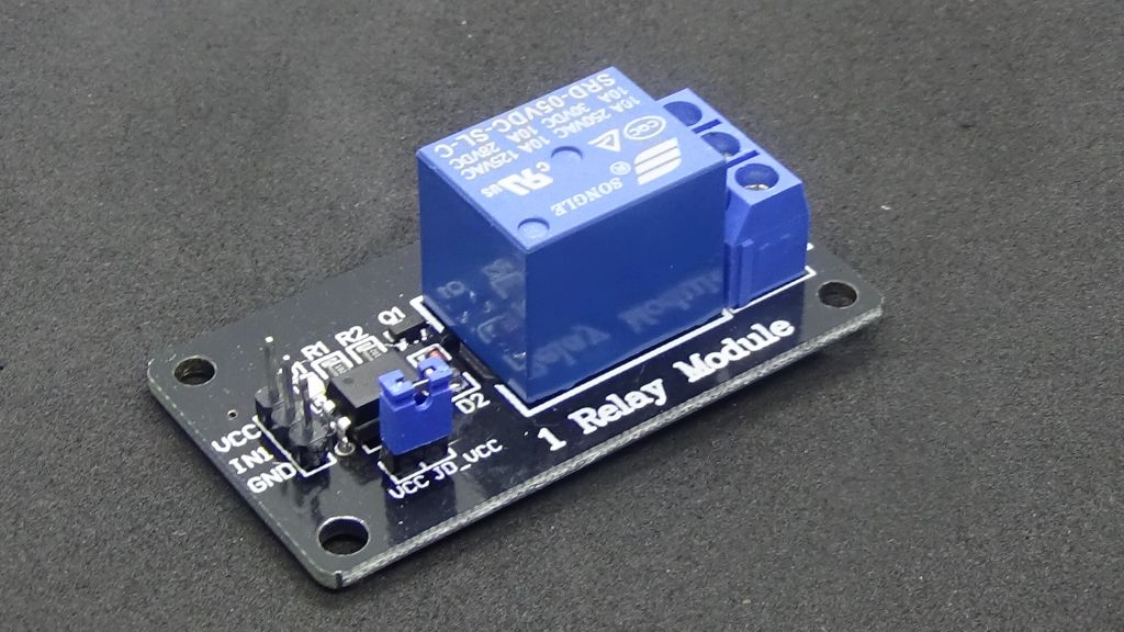
Relay modules are usually connected differently than you would expect. It is important to buy a module that suits your requirements. Some relays require higher voltages that Arduino can not deliver. Here is a relay that can be operated at a voltage of 5 V. The logic side has three terminals:
- VCC - Connects to the VCC on the Arduino.
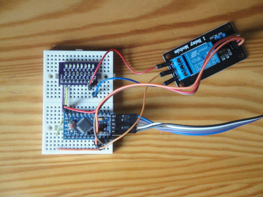
- IN - Connects to some digital pin on Arduine. The picture shows a pin that is attached to pin 9, located at the top left corner of the Arduino Pro Mini. I placed it there so I could add an 8 LED SMD board to the electrical circuit. The board visualizes logical states on the pin 9. If the logical one is on the pin, the red LED on the module is not illuminated. If the logical zero is on the pin, the red LED on the module lights up. This module with the relay is connected in such a way that a 1.5 mA current flows through the pin.
- GND - Connects to the G*ND on the Arduino.
There are three pins on the output side. On this module, they are not numbered but with small pictograms. They work so that pin 2-1 or pin 2-3 is always connected.
- Therefore, for example, it is advisable to connect the power supply to the center pin, and the module according to the value on the input connects the first or second pair.
- In the figure, the middle pin is connected to the VCC on the Arduino. The two rest pins are connected to two LEDs on the board. Through the board, the electrical circuit is closed to GND on the Arduino.
- This is what we can do if we use 5V everywhere. In the case of a 12V relay, we have to consider which pins we can connect to not destroy the Arduino.
The sketch
I have modified the Blink program to test the relay. The LED diode is on pin 9 and the intervals are set to 2 seconds. This gives you time to monitor relay behavior.
int led = 9;

void setup() {
  // initialize the digital pin as an output.
  pinMode(led, OUTPUT);
}

void loop() {
  digitalWrite(led, HIGH);   // turn the LED on (HIGH is the voltage level)
  delay(2000);               // wait for 2 second
  digitalWrite(led, LOW);    // turn the LED off by making the voltage LOW
  delay(2000);               // wait for 2 second
}
Source code
The source code is located on the GitHub server.
20.03.2018