NeoPixel Ring Clock - Basic Data
Zápisník experimentátora
Hierarchy: WS2812
LED clock made of NeoPixel ring and Arduino. In this article we will explain the basic connection and create the first version of the sketch. We're gonna need the Arduino Uno, one breadboard and NeoPixel Ring with twelve diodes. For example from Ebay.
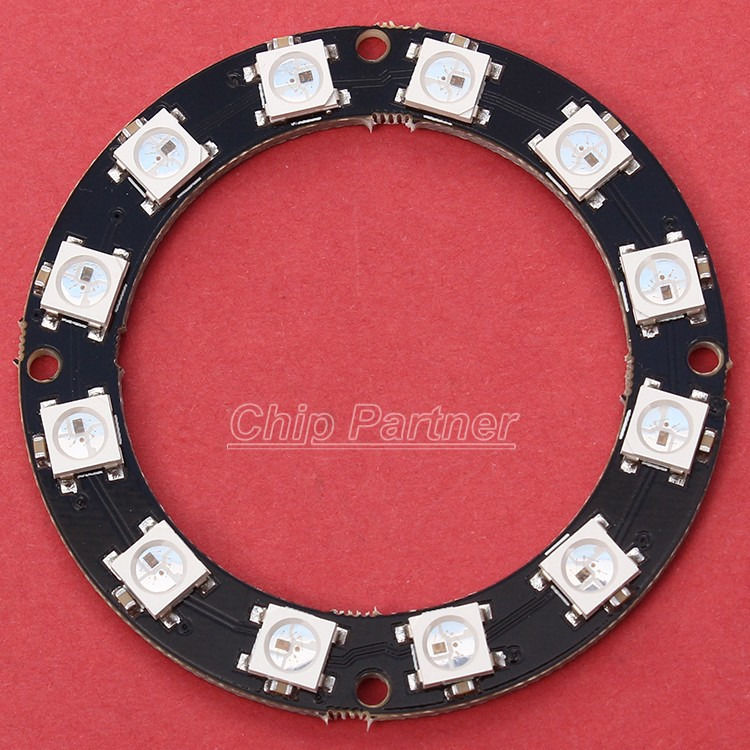
Soldering
NeoPixel Ring will be directly put in the breadboard, so it is necessary to solder four pins from the back side. Usually all soldering pads are in one place. Sometimes You can buy a ring, which has a soldering pads arranged differently. Don't panic, there are always four pads somewhere. Connect them in order as is mentioned in this article:
- Vcc - Connect this pin to +5 V.
- Gnd - Connect this pin to ground.
- Din - Connect this pin to digital pin 6. We will use it to send color change instructions.
- Dout - This pin will be unconnected. In case that we will have more rings, we can connect this pin into Din on the second ring.
Protection against damage
In the article Napájanie pre NeoPixel Ring You can read about rules for power supply. In this case we will not use high current, because at one moment will turn slightly just a few LEDs, so we can connect ring directly to Arduino. We will use protective capacitor between Vcc and Gnd and protective resistor between Arduino and Din.
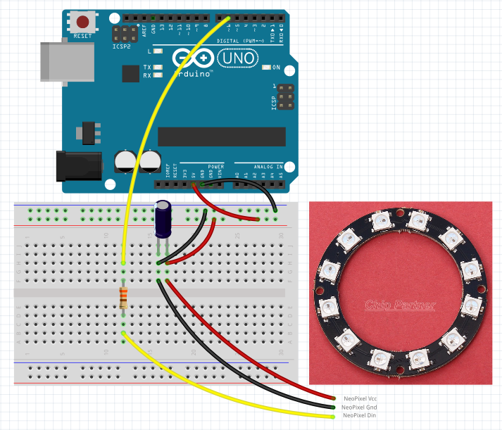
Scheme
Scheme is simple:
- Pin D6 is used to send commands. It is connected via protective resistor 330 R.
- Power supply pin uses protective capacitor 220 uF.
Sketch
The first version of the program will focus on the programming of basic functions:
- The points of light representing the hours, minutes, seconds and milliseconds - Setting the light points that represent the hands of the clock. Each point has its own color.
- Tail length for each point - If the needle is plotted using multiple LEDs, it may look better. It must however seek a compromise between length, because if we use four points with long tails, whole ring becomes visually disarranged.
- Minimizing energy consumption by reducing the brightness to the minimum - For the experiments we do not need to make the points very bright. Often we look at them up close and no one wants a burned points on the retina.
- Zero point shift to any position - This is a very important point, since the beginning of LED is usually near pin Din. But if we put ring into the breadboard, the whole thing is upside. Therefore, we will need function to move begining to another point.
- Settings simulated time after turning on - When testing do not need real time, as it would at some points quite often overlap. Therefore it will be more convenient for us, if you set a specific time during testing.
The inspiration was from video Arduino RGB LED Clock with Adafruit neopixel ring and from source code to it. I revised it, simplified it and removed bugs and added the missing parts.
Hours, minutes, seconds and milliseconds
The calculation is on the following line. We assume that our basic time is running in milliseconds. So all the calculations of the relative positions of the ring we have to make of this.
void NeoClock::Update()
{
// we use fake time
uint32_t m=millis()+60000L*STARTMINUTE+3600000L*STARTHOUR;

second = map ((m % 60000), 0, 60000, 0, CNT);
milli  = map ((m %  1000), 0,  1000, 0, CNT);
minute = map (((m/60000) % 60), 0,  60, 0, CNT);
hour =   map (((m/60000/60) % 12), 0,  12, 0, CNT);
}
Length of tail
We can choose whether we want to see the milliseconds that orbit fairly quickly, so it's more choice for effect. The two remaining option defines the tail 2 or 3 LEDs long. Except the seconds which are always long 3 LEDs.
// show milliseconds
#define SHOWMILLIS 0
// show long hour
#define SHOWLONGHOUR 0
// show long minute
#define SHOWLONGMINUTE 0
Minimum brightness
This it millisecond definition color. The maximum value is 255, which shines so strongly that you can not look to the naked eye. Red color is clearly visible in the indoor environment without direct sunlight. One LED consumes only about 20/255*10 mA. The whole ring with all the colors at full intensity consumes 12*3*20 mA, which is at limit of the USB port to which we have connected the Arduino.
uint32_t milli_color   = strip.Color ( 10,  0,  0);
uint32_t milli_color1  = strip.Color (  6,  0,  0);
uint32_t milli_color2  = strip.Color (  3,  0,  0);
Zero point shift
CNT is set to 12, because we use a ring of 12 LEDs. MOVE is set to 6, because on my version of the ring pins are located in one place and in the same place is placed first LED. Since the pins are inserted into the breadboard, we should have twelve rotated 180 degrees. The shift of six moves the starting point where we need it.
#define CNT 12
#define MOVE 6

void NeoClock::Draw()
{
Clear();

#if SHOWLONGHOUR
AddColor((hour+MOVE)     % CNT,  hour_color  );
AddColor((hour+MOVE-1)   % CNT,  hour_color1  );
AddColor((hour+MOVE-2)   % CNT,  hour_color2  );
#else
AddColor((hour+MOVE)     % CNT,  hour_color  );
AddColor((hour+MOVE-1)   % CNT,  hour_color2  );
#endif
Simulated time
On the following example we see the definition of the time 19:15. In the calculation it is then used real time from the start of the sketch to which it is added the adequate number of milliseconds.
#define STARTHOUR 19
#define STARTMINUTE 15
...
uint32_t m=millis()+60000L*STARTMINUTE+3600000L*STARTHOUR;
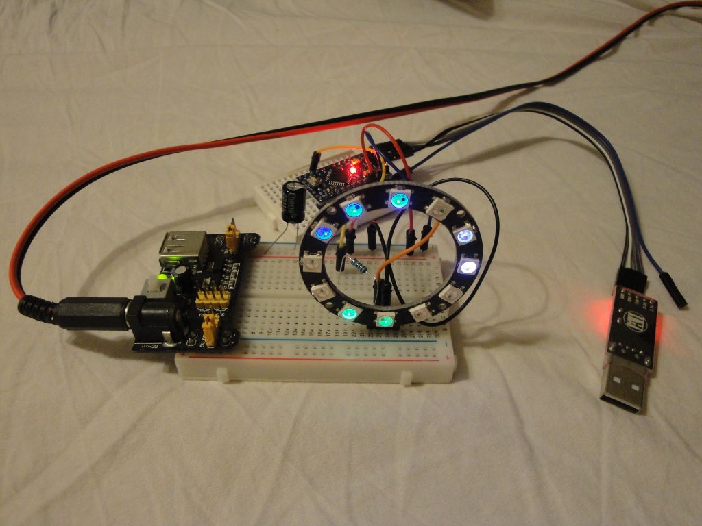
The remaining details can be found in the attached program. Next time we will look at adjusting brightness of LEDs that will be adapted to ambient light.
Download
- NeoPixel Ring Clock 01 Fritzing - Schema of Neopixel Ring Clock v. 1
- NeoPixel Ring Clock 01 Sketch - Sketch of NeoPixel Ring Clock v. 1
- WS2812 - Datasheet WS2812 - Intelligent control LED integrated light source
- WS2812B - Datasheet WS2812B - Intelligent control LED integrated light source
22.07.2015