Visualization of TCNT0 register activity in CTC mode
Zápisník experimentátora
Hierarchy: Časovač (timer)
In this article, we build on the previous article that described timer2. We will try to visualize the operation of the TCNT0 register, which is located in timer 0. Timer0 in Arduino handles the time calculation and therefore the operations on it also affect the millis and delay functions. We will show you a simple solution to deal with such a problem.
Used parts
To create an animation we can use:
- Arduino Pro Mini (link) - I used it because it will fit even the smallest breadboard.
- Mini Breadboard (link) - The smallest sold breadboard. I used two and be careful that two modifications of this breadboard are sold. Those with small protrusions can be nicely connected to each other in this way.
- Converter CP2102 USB to Serial (link) - The converter is used to program the Arduino.
- Board with resistors and LEDs (link) - Since I have made several such boards, I used it so that I did not have to complicatedly connect 8 LEDs and 8 resistors to the Arduino pins. But you can also use resistors and LEDs directly, just be careful not to exceed the maximum current on the pin. Therefore, use resistors from 330 to 1000 ohms.
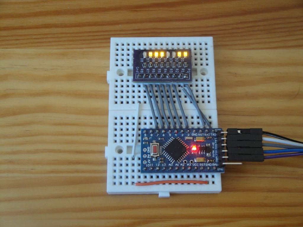
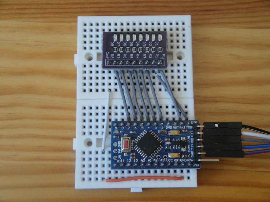
Everything is connected according to the following picture. The LEDs are connected to pins RX (0), TX (1), 2-7 and the picture also shows the GND connection on my LED board using two wire jumpers to the Arduino. The Arduino Pro Mini also has GND on the other side, so I could have used a single jumper, but then it would be badly photographed.
RX and TX are swapped because the bit of the 8-bit number will be displayed by writing directly to the PORTD register, and we need to have the pins aligned the same as the bits in the register. We will display the contents of the TCNT0 register, which is the register for timer0. In it, the value gradually increases up to the set value of the OCR0A register. This happens in the case of CTC mode. It should be true that the maximum value of TCNT0 = OCR0A. This is easy to check on the diodes, because if you write the value 63 (binary 0b00111111) to OCR0A, for example, the last two LEDs should not light up. If they light up, then you have programmed something wrong.
Programming
This program affects timer0 and therefore the millis and delay functions cannot be used in it.
I generated the basis of the program in my application. Because the Arduino clock is set to 16 MHz and we use an 8-bit timer, we cannot set it too low. The minimum is approximately 70 Hz. That's why I set it to 100 Hz.
In order to see that the program is working properly, I also let the LED on pine 13 flash in the program. The flashing takes place in the ISR interrupt handler (TIMER0_COMPA_vect) and since the interrupt is triggered 100 times per second, I slowed it down using a variable divider to 1 Hz.
The interrupt visualization is in the loop function. We can't have it in an interrupt, because the TCNT0 register still has the same value when the interrupt is triggered. In the previous example, I delayed the entry at the register slightly at this point using the delay function. But we can't use it now, because I reprogrammed the timing of timer 0 and thus changed the time calculation for Arduino. For example, the delay function is defined in the Arduino core as follows.
void delay(unsigned long ms)
{
    uint32_t start = micros();

    while (ms > 0) {
        yield();
        while ( ms > 0 && (micros() - start) >= 1000) {
            ms--;
            start += 1000;
        }
    }
}
Because in this case I only need some deceleration, I just need to use the nop instruction in sufficient quantity. I used a cycle that uses this instruction in sufficient quantity to slow down the rendering for a few milliseconds to achieve the desired effect. The text in quotation marks must also be written with \n at the end, because the assembler instructions are each written on a separate line and this will ensure us. When we have only one instruction, it is not as visible as if we used them more than once in the code.
for(long i=0;i<100000;i++)
    __asm__("nop\n");
This created an interesting animation effect. It's a bit like old sci-fi movies, where spaceships, or any advanced technology, used to be displayed as a flashing group of lights.
When you look at the blinking, you will notice that the binary number does not go up to 255. If, for example, the value 31, 63 or 127 were in the OCR0A register, the LEDs from the upper bits would be even more visible. This is actually proof that it really counts correctly in CTC mode.
#define ledPin 13

int divider=0;

void setupTimer() {
  noInterrupts();
  TCCR0A = 0;
  TCCR0B = 0;
  TCNT0  = 0;

  OCR0A = 155; // 100.16025641025641 Hz
  TCCR0A |= (1 << WGM01);
  TCCR0B |= 0;
  TCCR0B |= (1 << CS02) | (0 << CS01) | (1 << CS00);
  TIMSK0 |= (1 << OCIE0A);
  interrupts();
}

void setup() {
  pinMode(ledPin, OUTPUT);

  for (int i = 0; i < 8; i++)
    pinMode(i, OUTPUT);

  setupTimer();
}

void loop() {
  PORTD = TCNT0;

  // delay replacement, because we changed timer0
  for(long i=0;i<100000;i++)
    __asm__("nop\n");
}

ISR(TIMER0_COMPA_vect) {
  if(divider==0)
    digitalWrite(ledPin, digitalRead(ledPin) ^ 1);
  divider++;
  divider%=100;
}
Source code
The source code is on the server GitHub.
31.05.2020