DS1307 and ESP8266
Zápisník experimentátora
Hierarchy: DS1307 Hodiny reálneho času
In the datasheet of the DS1307, you will read that the recommended power supply of the integrated circuit is in the range of 4.5 - 5 V. On the Internet, however, you will find many examples of connecting this integrated circuit to the ESP8266, where no power problem is reported. Let's see if the DS1307 is able to work with ESP8266 without any problems.
Datasheet DS1307
You can find this alert in the datasheet. If I understand it correctly, when the circuit power drops below 4V, the circuit should not communicate with the microcontroller because it uses the reference voltage on the battery to see if it is connected to a voltage source.
Vcc - Primary Power Supply. When voltage is applied within normal limits, the device is fully accessible and data can be written and read. When a backup supply is connected to the device and VCC is below VTP, read and writes are inhibited. However, the timekeeping function continues unaffected by the lower input voltage.
When VCC falls below 1.25 x VBAT, the device terminates an access in progress and resets the device address counter. Inputs to the device will not be recognized at this time to prevent erroneous data from being written to the device from an out-of-tolerance system. When VCC falls below VBAT, the device switches into a lowcurrent battery-backup mode. Upon power-up, the device switches from battery to VCC when VCC is greater than VBAT +0.2V and recognizes inputs when VCC is greater than 1.25 x VBAT.
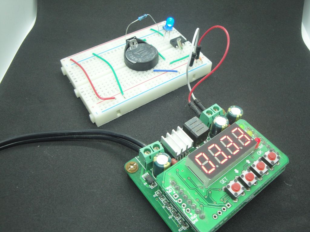
In order to test what is going on, I used the mode setting with the square wave output. I wrote about in the previous article. I set the voltage source (B3603) to 5V and connected it to the circuit. The blue LED flashes. I gradually lowered the voltage to 3.3 V and the LED was still blinking. This test verified that the SQW output works even at lower voltages.
I2C scanner
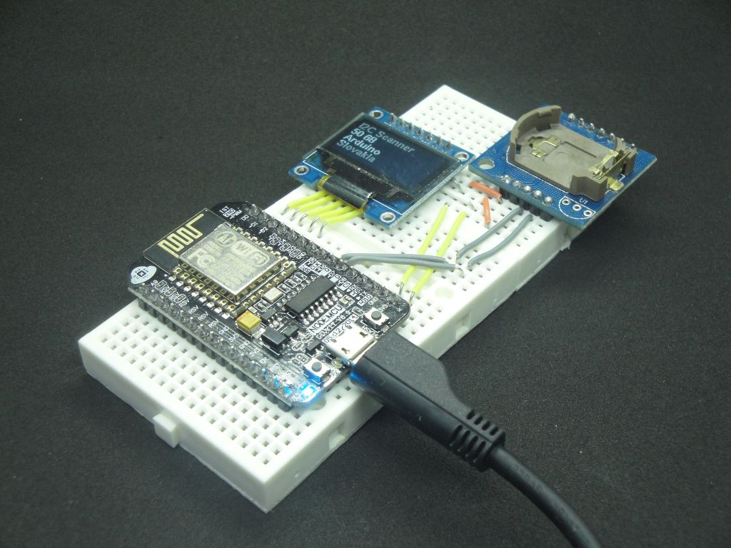
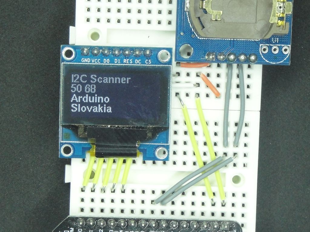
Then I continued the test using the I2C scanner. It can detect any i2C slave device. Because I recently found a more sophisticated solution than the commonly used scanner for Arduino, I used the scanner (i2cdetect), which is used on Linux on single board minicomputers. I rewrote it for Arduino. And because one ESP8266 and OLED display left me from previous experiments, I wrote one version for this combination too. A whole table is displayed on the serial port and only the addresses found on the OLED display. The tester's source code is located on the GitHub server.
And I2C test was successful and ESP8266 found connected DS1307 circuit. Because I used the module, scanner olso found a connected external EEPROM.
But then I thought I did not have a battery in the module. Therefore, the conditions in the datasheet were met. Vcc was always higher than on the battery. That's why I tried to connect the DS1307 to a breadboard where I have a battery attached. And there it did not work. If the Vcc was 3.3 V, the SQW output did work, but the I2C communication did not work. When I connected the Vcc to 5 V, the circuit started to communicate.
See the picture below. If you use 5 V logic, you will have it connected as follows. Vcc is connected directly to 5 V and SDA and SCL are connected via pull-up resistors. If you use ESP8266 that uses 3.3V, you can not connect any of its pins to 5V. So, SDA and SCL must be connected via a pull-up to 3.3V. But the Vcc of the DS1307 must be connected to 5V.
This makes it possible to get involved only on the breadboard. If you use a module, it always has internal pull-up resistors connected to its Vcc. And so you can not connect SDA and SCL to ESP8266, because you risk that you burn something in it.

Download
- DS1307 - Datasheet DS1307 - 64 x 8 Serial Real-Time Clock
13.10.2017