ESP8266 - Thermometer with DS18B20
Zápisník experimentátora
Hierarchy: ESP8266
In today's article, I would like to start working on a simple thermometer theme, which I will gradually improve. In the first article we create a simple thermometer with the ESP8266 microcontroller and the DS18B20 integrated circuit. The result will be displayed on the OLED display. This basic circuit will also serve us in other articles in which we will try to send the collected temperature data to the Internet into a service that is designed to collect and visualize bulk data.
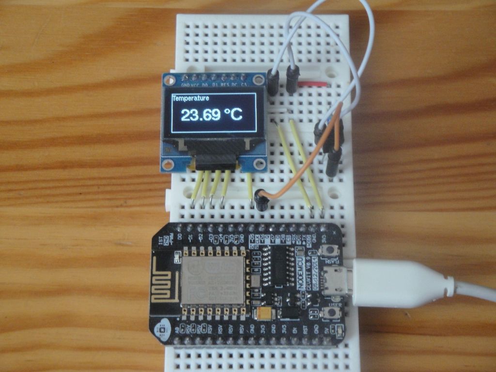
I used the combination of the ESP8266 microcontroller and the OLED display to make the result more interesting. ESP8266 has a WiFi connection, so it's logical if the measurement results are sent over HTTP to a remote server. This is the first article in the series and it deals with the construction of the thermometer itself. And because there is also a companion video, the video looks better when you can see the temperature on the display.
The integrated circuit DS18B20 is used to measure the temperature. It is able to work in two modes.
- Normal power supply.
- Parasitic power supply.
If you use Arduino, you can use both modes. Arduino is able to use a relatively large current across the pin, which is capable of feeding an integrated circuit even in a parasitic power supply. ESP8266 works at a lower voltage and allows a much lower current through the pin. As a result, you can not use parasitic power. This can only be done by adjusting the circuit, which needs to be supplemented by other components, and we will not engage in such engagement. It does not make sense for our purposes. In addition, DS18B20 versions (probably Chinese imitations or discarded circuits) have been emerging recently and have problems with parasitic power supply.
Used parts
I used these components.
- ESP8266 (NodeMCU v. 0.9)
- Breadboard
- DS18B20
- OLED display SPI 0.96
Used libraries
I installed the core for ESP8266 in the Arduino IDE.
I used these libraries. All can be installed using Library Manager.
- U8g2 - OLED display control.
- OneWire - One Wire protocol.
- DallasTemperature - Sensor control DS18B20.
Program
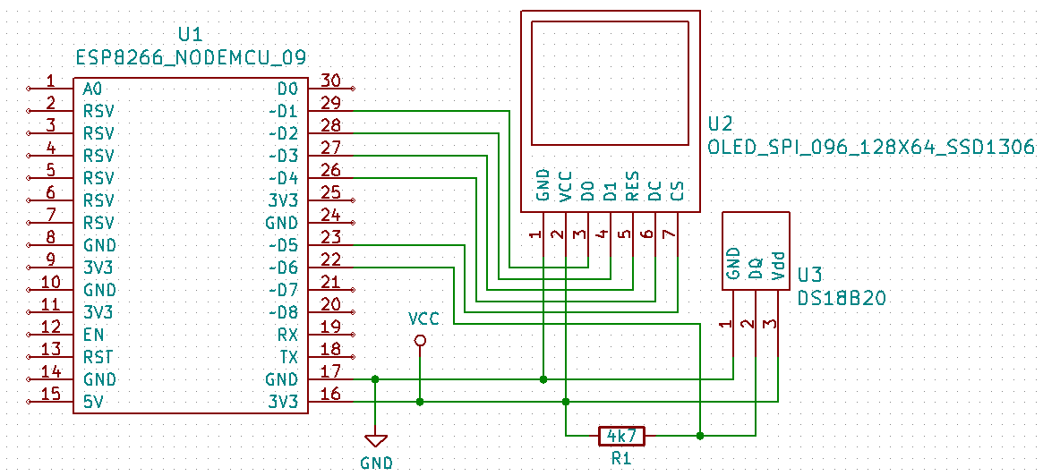
The program is simple. ESP8266 has a limited number of digital pins, so I also use a pin layout that copies the pin assignment on the NodeMCU board. 5 pins are used to connect the display. One pin is used to connect the integrated circuit DS18B20, which measures the temperature. Initially, the program initializes the OLED display and the OneWire bus. It then displays the text information on the display. Two states can then occur.
- If no sensor has been connected to the program, it will display an error message on the display.
- If the program finds a temperature sensor, the display will show the measured temperature every second. The interval is set to show the sensor response in the video. In practice, it is enough to measure the temperature at longer intervals.
#include <U8g2lib.h>
#include <OneWire.h>
#include <DallasTemperature.h>

#define ONE_WIRE_BUS D6

OneWire oneWire(ONE_WIRE_BUS);
DallasTemperature sensors(&oneWire);

U8G2_SSD1306_128X64_NONAME_F_4W_SW_SPI u8g2(U8G2_R0, /* clock=*/ D1, /* data=*/ D2, /* cs=*/ D5, /* dc=*/ D4, /* reset=*/ D3);
char draw[30];

#define LINE0 11
#define LINE1 22
#define LINE2 33
#define LINE4 44
#define LINE5 55

void setup() {
  u8g2.begin();
  u8g2.enableUTF8Print();
  u8g2.setFont(u8g2_font_helvR08_tf);

  u8g2.clearBuffer();
  u8g2.drawStr(0, 12, "Arduino Slovakia");
  u8g2.drawStr(0, 26, "DS18B20 Thermometer");
  u8g2.sendBuffer();

  sensors.begin();
  sensors.setResolution(12);

  Serial.begin(115200);

  delay(1000);

  Serial.println("Setup done");
}

void loop() {
  if (sensors.getDS18Count() != 0) {
    sensors.requestTemperatures();
    double temp = sensors.getTempCByIndex(0);
    Serial.println(temp);

    u8g2.clearBuffer();
    sprintf(draw, "Temperature");
    u8g2.setFont(u8g2_font_helvR08_tf);
    u8g2.drawUTF8(1, LINE0, draw);
    sprintf(draw, "%.02f °C", temp);
    u8g2.setFont(u8g2_font_helvB18_tf);
    u8g2.drawUTF8(15, LINE4, draw);
    u8g2.drawFrame(0, 0, 128, 64);
    u8g2.sendBuffer();
  }
  else {
    u8g2.clearBuffer();
    u8g2.setFont(u8g2_font_helvR08_tf);
    u8g2.drawUTF8(1, LINE0, "Error");
    u8g2.drawFrame(0, 0, 128, 64);
    u8g2.sendBuffer();
  }
  delay(1000);
}
Source code
The source code is located on the GitHub server.
Video
The video is located on YouTube.
- to-do
30.01.2019