ATtiny85 development board on a breadboard
Zápisník experimentátora
Hierarchy: ATtiny85
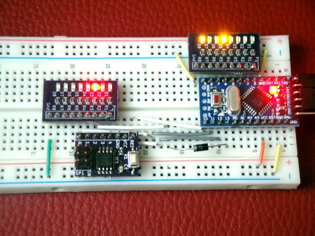
I recently introduced a SMD development board for the ATtiny85 microcontroller on these pages. In today's article I would like to show it in action. This development board has been incorporated into my other boards that I use on breadboard. I made them so that I do not need to constantly insert a large number of wire leads into the breadboard. Their quantity is reduced to a minimum. It is also visible on the illustrative photo.
Used parts
In this article, we will show the photos of the development board that is programmed using the Arduino. I have the following boards on breadboard:
- Arduino Pro Mini (link) - The sketch
ArduinoISPis in the Arduino. The ArduinoISP program uses 3 pins to signal the programming of the target microcontroller. Because they are on pins 7, 8 and 9, I have attached the following LED board to them. - SMD board with eight yellow LEDs (link) - There are 8 LEDs on the board. Of this, 3 are used to indicate programming. This is how the ArduinoISP program signals its activity. The fourth LED lights up in the picture, but only because I experiment with this program and adapt it to my needs. Note that due to the appropriate board design, only one connecting wire is needed, which is connected to the GND.
- SMD board with ATtiny85 microcontroller (link) - You can find the procedure for making the board by clicking hypertext. The board has one row of pins. It is connected to the Arduino using four interconnecting wires. Below the board there are two interconnecting wires that are connected to the VCC and GND on the board. Four connecting wires are connected to the Arduino pins 10, 11, 12 and 13. The circuit diagram is found in the article Arduino as an ISP programmer. There is a difference in the photo. Pin 13 is not connected by a interconnecting wire, but by a diode.
- SMD board with eight red LEDs (link) - The same board with LEDs is attached to the pins of the ATtiny85 board. LEDs serve for rapid development on microcontrollers. With the eye, you can immediately see if the output is switched to a logical one or logical zero.
- 1x diode 1N4007 (link) - Pin 13 is not connected by a interconnecting wire, but by a diode. That's because, during the experiments, I found that just after the Arduino is turned on, the pin is set to some logical state and is not in high impedance. If ATtiny85 runs a program that handles pin 2, the LED diode also flashes on the Arduino. Diode does not matter programming (diode reduces voltage by only 0.7 V, which ATtiny85 still reads as a logical one.). ATtiny85 does not affect the Arduino. This is a strange behavior that disapears after the first ATtiny85 programming after switching on. I did not have time to check ArduinoISP for the exact cause of the problem.
Sample program
A simple program is appropriate to test the connection. In this case it is a program that will gradually turn on the LEDs on the pins 0-4.
const int leds[] = {0, 1, 2, 3, 4};
const int ledcount = sizeof(leds) / sizeof(int);
int step = 0;
const int sleep = 200;

// the setup routine runs once when you press reset:
void setup() {
  for (int i = 0; i < ledcount; i++)
    pinMode(leds[i], OUTPUT);
}

void loop() {
  for (int i = 0; i < ledcount; i++)
    digitalWrite(leds[i], i == step ? HIGH : LOW);
  step++;
  step %= ledcount;
  delay(sleep);
}
Video
Source code
The source code is located on the GitHub server.
Video
05.07.2021