NeoPixel Ring HSV - Return of rotating circles
Zápisník experimentátora
Hierarchy: WS2812
In the discussion of the video about rotating circles the question was raised whether the red color could not be adjusted to other colors. This article is about finding the right color. Using three potentiometers, you can customize the basic HSV color model and you can also set the rotation speed.
![]()
Used parts
- Arduino Uno - You can use any version of the Arduino.
- NeoPixel Ring 24 LED (link) - Includes 24 RGB LEDs with WS2812B chip.
- Resistor 1k (link) - The resistor is attached to the NeoPixel Ring data input. It serves as a pin protection.
- Capacitor 220 uF (link) - The capacitor is connected between VCC and GND on NeoPixel Ringu. It is used to straighten the voltage peaks.
Protective components are necessary in order to not damage NeoPixel Ring. Details of protection are in article on powering these diodes.
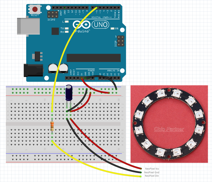
The picture shows a ring with 12 diodes. Ring with 24 diodes is not very different from it and it is therefore possible to use a smaller ring after minor changes in the sketch.
The sketch
Against the previous program, I added reading of three analogue potentiometer values. I use better potentiometers that are used in audiotechnics. I also chose the ones that are designed to slide from the top to the circuit board. They have a value of 10k and when rotating the shaft, they have a stop in the middle of the track, which makes it easier to orientate.
Plug-in potentiometers are not science unless you observe the basic rule that the analog parts of the circuit are in a different branch than the digital one. In this case, the digital part represents the NeoPixel Ring. This type, which has 24 LEDs, can take up to 3x24x20 mA when all diodes are on. Therefore, it is advisable to put it on the breadboard on one side. The analogue part has to be put in the second part. If you did not, you could measure strange values at analog inputs. This is due to the fact that the breadboard has a considerable resistance in the metallic paths and joints, and so with a large flowing current there will be a great drop in voltage.
In my circuit, another capacitor at the outermost potentiometer is added to ensure better measurement. And because I measure more than one analog value, I ignore the first measurement and the resulting value averages out of the four measurements. Measured values in the range 0-1023 are transformed by the function map into appropriate ranges.
Once per second I write all measured values to the serial port. I use the function sprint to make it easier to write.
#include <Adafruit_NeoPixel.h>
#include "hsv.h"

// data pin
#define PIN 6
// led count
#define CNT 24
// max Hue
#define MAXHUE 256*6

int position = 0;
int pot_hue;        // A0
int pot_saturation; // A2
int pot_speed;      // A3
char output[128];
unsigned long next_time = 0;

Adafruit_NeoPixel strip = Adafruit_NeoPixel(CNT, PIN, NEO_GRB + NEO_KHZ800);

void setup() {
  Serial.begin(115200);
  strip.begin();
}

void loop() {
  // analog
  pot_hue = map(aRead(A0), 0, 1023, 0, MAXHUE);
  pot_saturation = map(aRead(A2), 0, 1023, 0, 255);
  pot_speed = map(aRead(A3), 0, 1023, 1, 500);
  unsigned long m = millis();
  if (m - next_time > 1000L) {
    next_time = m;
    sprintf(output, "hue: %d, sat: %d, spd: %d", pot_hue, pot_saturation, pot_speed);
    Serial.println(output);
  }

  // hue - red
  // saturation - max
  // value - 0-255
  for (int i = 0; i < CNT; i++)
    strip.setPixelColor((i + position) % CNT,
                        getPixelColorHsv(i,
                                         pot_hue,
                                         pot_saturation,
                                         strip.gamma8(i * (255 / CNT))));
  strip.show();
  position++;
  position %= CNT;
  delay(pot_speed);
}

int aRead(int anl) {
  long tmp = 0, t;
  // discard first X measurements
  for (int i = 0; i < 1; i++)
    analogRead(anl);
  for (int i = 0; i < 4; i++) {
    t = analogRead(anl);
    tmp += t;
  }
  return tmp / 4;
}
Video
Original video and new video with potentiometers.
![]()
Source code
The source code is located on the GitHub server.
Video
15.08.2018